
TM 5-3805-264-13&P
0051
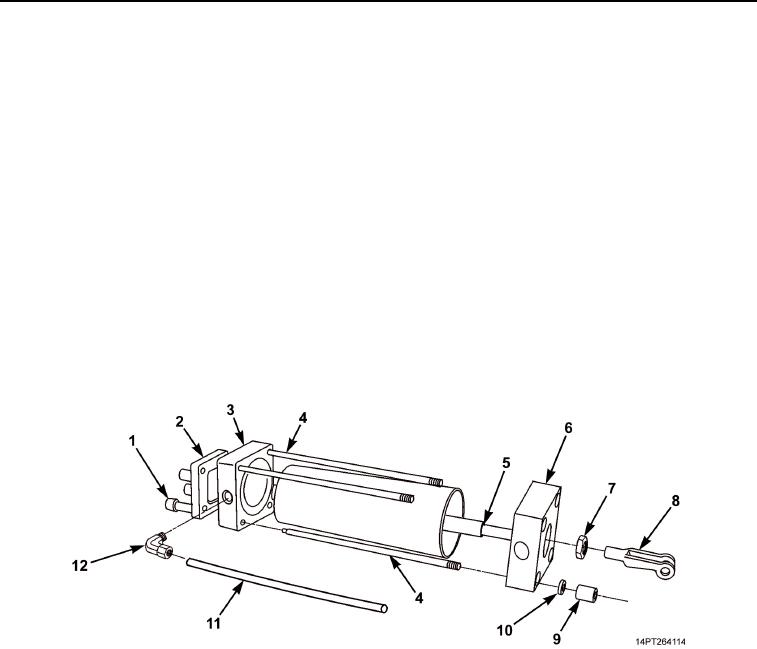
DISASSEMBLY
1.
Remove tube (Figure 1, Item 11) from elbow (Figure 1, Item 12).
2.
Remove elbow (Figure 1, Item 12) from top end plate (Figure 1, Item 3).
3.
Remove four screws (Figure 1, Item 1) and mounting bracket (Figure 1, Item 2) from top end plate
(Figure 1, Item 3).
NOTE
Note position of nut at air cylinder piston shaft clevis during removal to ensure proper
adjustment of air cylinder during installation.
4.
Remove clevis (Figure 1, Item 8) and nut (Figure 1, Item 7) from piston shaft (Figure 1, Item 5).
5.
Remove four retaining nuts (Figure 1, Item 9) and lockwashers (Figure 1, Item 10) from tie rods
(Figure 1, Item 4). Discard lockwashers.
6.
Remove top end plate (Figure 1, Item 3) with tie rods attached from bottom end plate (Figure 1, Item 6).
7.
Separate bottom end plate (Figure 1, Item 6) from piston shaft (Figure 1, Item 5).
8.
Remove tie rods (Figure 1, Item 4) from top end plate (Figure 1, Item 3).
Figure 1. MCS Air Cylinder.
03/15/2011Rel(1.10)root(maintwp)wpno(M1002426413)