
TM 5-3805-264-13&P
0051
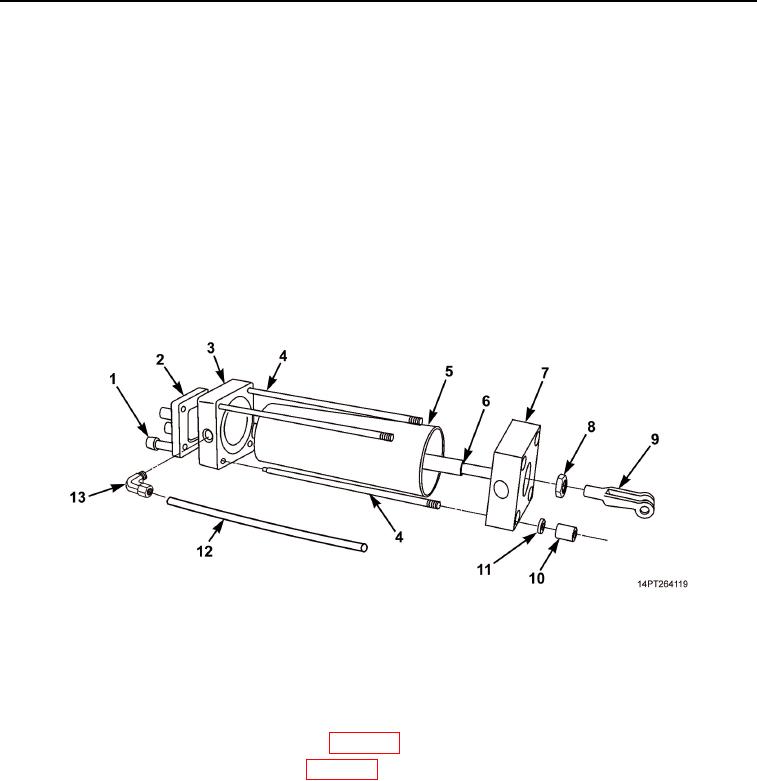
ASSEMBLY - Continued
11.
Install tie rods (Figure 6, Item 4) on top end plate (Figure 6, Item 3).
12.
Position cylinder sleeve (Figure 6, Item 5) with piston on top end plate (Figure 6, Item 3).
13.
Slide bottom end plate (Figure 6, Item 7) on piston shaft (Figure 6, Item 6).
14.
Install four new lockwashers (Figure 6, Item 11) and four retaining nuts (Figure 6, Item 10) on tie rods
(Figure 6, Item 4).
15.
Install nut (Figure 6, Item 8) and clevis (Figure 6, Item 9) on piston shaft (Figure 6, Item 6) in same position
as removal.
16.
Install mounting bracket (Figure 6, Item 2) and four screws (Figure 6, Item 1) on top end plate
(Figure 6, Item 3).
17.
Install elbow (Figure 6, Item 13) on top end plate (Figure 6, Item 3).
18.
Install tube (Figure 6, Item 12) on elbow (Figure 6, Item 13).
Figure 6. MCS Air Cylinder Assembly.
END OF TASK
FOLLOW-ON MAINTENANCE
1.
Install MCS air cylinder solenoid assembly (WP 0050).
2.
Install tailgate release/MCS air cylinder (WP 0051).
END OF TASK
END OF WORK PACKAGE
03/15/2011Rel(1.10)root(maintwp)wpno(M1002426413)