
TM 5-3805-264-13&P
0051
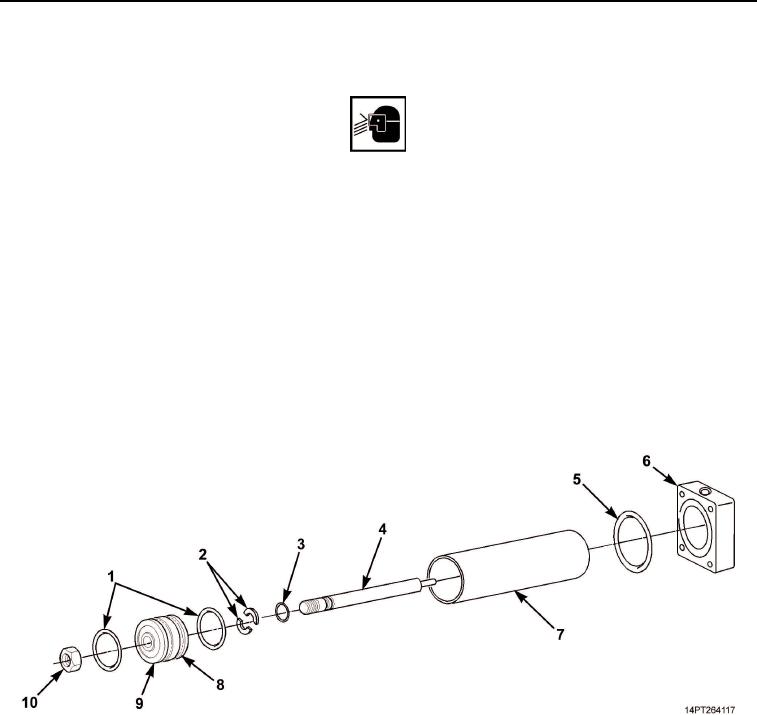
ASSEMBLY
WARNING
Eye protection and gloves must be worn when using grease or lubricating oils. Failure to
comply may result in personnel injury.
1.
Apply a light coat of grease to new preformed packing (Figure 4, Item 3) and install on piston shaft
(Figure 4, Item 4).
2.
Apply a light coat of grease to piston (Figure 4, Item 9).
3.
Install two new plain seals (Figure 4, Item 1) and new metal strip (Figure 4, Item 8) on piston
(Figure 4, Item 9).
4.
Install metal washer (Figure 4, Item 2) halves on piston shaft (Figure 4, Item 4) and install piston
(Figure 4, Item 9) on piston shaft.
5.
Install nut (Figure 4, Item 10) on piston shaft (Figure 4, Item 4).
6.
Install cylinder sleeve (Figure 4, Item 7) on piston (Figure 4, Item 9).
7.
Install new preformed packing (Figure 4, Item 5) on bottom end plate (Figure 4, Item 6).
Figure 4. Cylinder Piston Assembly.
03/15/2011Rel(1.10)root(maintwp)wpno(M1002426413)