
TM 5-3805-264-13&P
0050
ASSEMBLY - Continued
5.
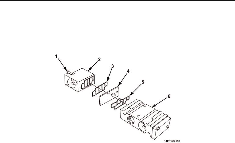
Install new gasket (Figure 7, Item 5) on valve body (Figure 7, Item 6).
6.
Install new gasket (Figure 7, Item 3) on filter housing (Figure 7, Item 2).
7.
Position metal gasket (Figure 7, Item 4) and filter housing (Figure 7, Item 2) on valve body (Figure 7, Item 6)
and install two screws (Figure 7, Item 1).
Figure 7. Valve Body Filter and Components Assembly.
03/15/2011Rel(1.10)root(maintwp)wpno(M1002326413)