
TM 5-3805-264-13&P
0054
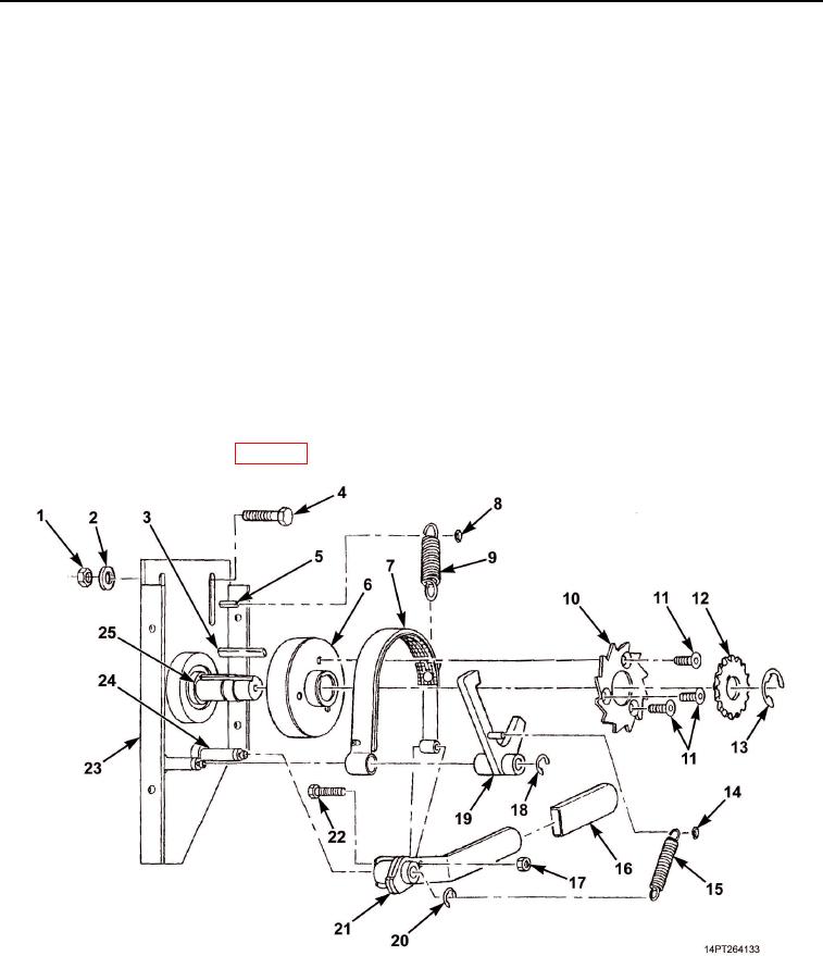
ASSEMBLY - Continued
5.
Install handle grip (Figure 1, Item 16) on control handle (Figure 1, Item 21).
6.
Position brake band (Figure 1, Item 7) over brake drum (Figure 1, Item 6). Position control handle
(Figure 1, Item 21) on pivot shaft (Figure 1, Item 24).
7.
Install brake pawl (Figure 1, Item 19) on crank assembly baseplate (Figure 1, Item 23) with retaining ring
(Figure 1, Item 18).
8.
Install brake pawl spring (Figure 1, Item 15) between control handle (Figure 1, Item 21) and brake pawl
(Figure 1, Item 19). Secure brake pawl spring to pawl with new locknut (Figure 1, Item 14). Secure to control
handle with retaining ring (Figure 1, Item 20).
9.
Install brake band spring (Figure 1, Item 9) between brake band (Figure 1, Item 7) and crank assembly
baseplate stud (Figure 1, Item 5). Secure with new locknut (Figure 1, Item 8).
END OF TASK
INSTALLATION
1.
Install crank assembly baseplate (Figure 1, Item 23) on dump body with two screws (Figure 1, Item 4), new
lockwashers (Figure 1, Item 2), and nuts (Figure 1, Item 1). Do not tighten screws.
2.
Install chain on sprockets (WP 0055) and tighten screws (Figure 1, Item 4).
Figure 1. Cargo Cover Crank.
END OF TASK
03/15/2011Rel(1.10)root(maintwp)wpno(M1003126413)