
TM 5-3805-264-13&P
0055
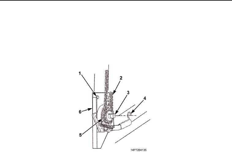
REMOVAL - Continued
3.
Loosen crank assembly baseplate mounting screws (Figure 2, Item 1).
4.
Raise crank assembly baseplate (Figure 2, Item 6) and remove chain (Figure 2, Item 2) from sprocket
(Figure 2, Item 5).
5.
Remove retaining ring (Figure 2, Item 4) and sprocket (Figure 2, Item 5) from crankshaft (Figure 2, Item 3).
Discard retaining ring if damaged.
Figure 2. Crank Hardware Removal.
03/15/2011Rel(1.10)root(maintwp)wpno(M1003226413)