
TM 5-3805-264-13&P
0055
INSTALLATION - Continued
7.
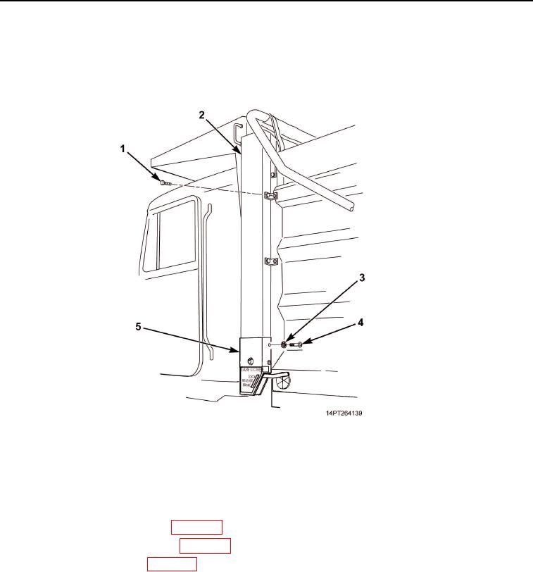
Install chain cover (Figure 6, Item 2) with four screws (Figure 6, Item 1).
8.
Install crank assembly cover (Figure 6, Item 5) with four new lockwashers (Figure 6, Item 3) and screws
(Figure 6, Item 4).
Figure 6. Cover Installation.
END OF TASK
FOLLOW-ON MAINTENANCE
1.
Install crank handle assembly (WP 0054).
2.
Check operation of cargo cover (WP 0005).
3.
Fully retract cargo cover (WP 0005).
END OF TASK
END OF WORK PACKAGE
03/15/2011Rel(1.10)root(maintwp)wpno(M1003226413)