
TM 5-3805-264-13&P
0055
INSTALLATION - Continued
3.
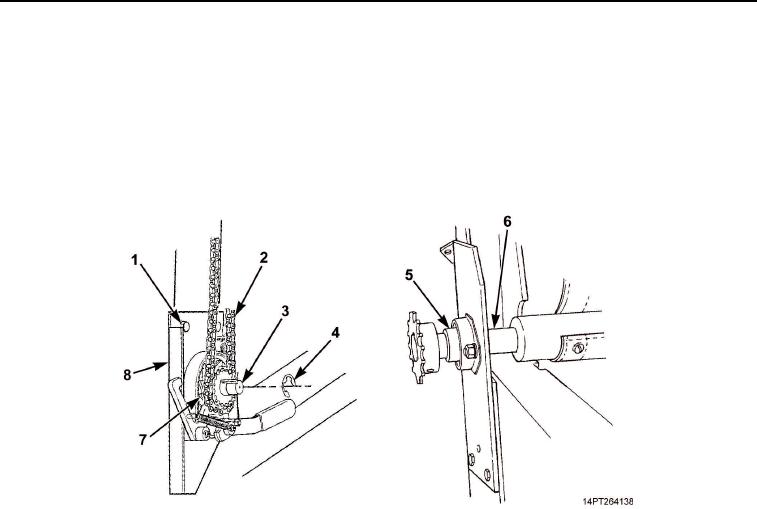
Install sprocket (Figure 5, Item 7) on crankshaft (Figure 5, Item 3) with retaining ring (Figure 5, Item 4).
4.
Raise baseplate (Figure 5, Item 8) and position chain (Figure 5, Item 2) under sprocket (Figure 5, Item 7).
5.
Lower baseplate to put tension on chain. Tighten mounting screws (Figure 5, Item 1).
6.
Apply sealing compound sparingly to chain (Figure 5, Item 2) and to roller shaft bearings (Figure 5, Item 5)
on both ends of roll-up bar (Figure 5, Item 6).
Figure 5. Crank Hardware Installation.
03/15/2011Rel(1.10)root(maintwp)wpno(M1003226413)