
TM 5-3805-264-13&P
0056
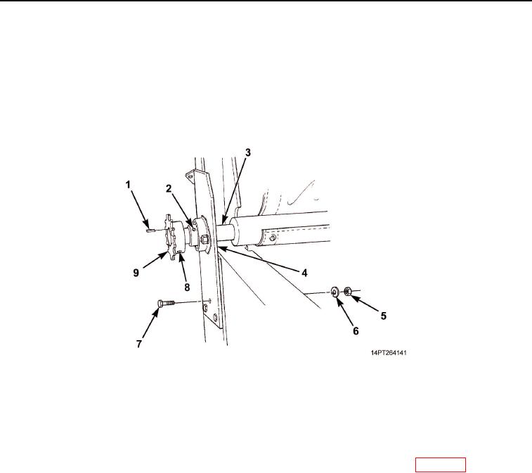
REMOVAL - Continued
5.
Loosen set screw (Figure 2, Item 8) and remove sprocket (Figure 2, Item 9) with sprocket alignment key
(Figure 2, Item 1) from roll-up bar (Figure 2, Item 3).
6.
Remove three nuts (Figure 2, Item 5), lockwashers (Figure 2, Item 6), and screws (Figure 2, Item 7) from
driver's side mounting bracket (Figure 2, Item 4) and dump body. Discard lockwashers.
7.
Loosen set screw (Figure 2, Item 2) at each end of roll-up bar (Figure 2, Item 3). Remove driver's side
mounting bracket (Figure 2, Item 4) and roll-up bar. Slide bracket from roll-up bar.
Figure 2. Roll-Up Bar Removal.
END OF TASK
CLEANING AND INSPECTION
Clean and inspect all components in accordance with General Maintenance Instructions (WP 0072).
END OF TASK
03/15/2011Rel(1.10)root(maintwp)wpno(M1003326413)