
TM 5-3805-264-13&P
0056
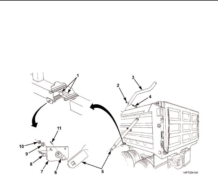
REMOVAL
1.
Remove rubber strap from connecting arm (Figure 1, Item 3) and swing arm (Figure 1, Item 5).
2.
Remove machine key (Figure 1, Item 11) from shaft (Figure 1, Item 6) on spring assembly
(Figure 1, Item 7). Remove swing arm (Figure 1, Item 5) from shaft. Discard machine key.
3.
Remove locknut (Figure 1, Item 2) and eyebolt (Figure 1, Item 4) and separate swing arm (Figure 1, Item 5)
and connecting arm (Figure 1, Item 3). Discard locknut.
4.
Remove two nuts (Figure 1, Item 10), lockwashers (Figure 1, Item 9), and screws (Figure 1, Item 8) from
spring assembly (Figure 1, Item 7). Remove spring assembly from dump body and from welded shaft
support bar and tube (Figure 1, Item 1). Discard lockwashers.
Figure 1. Roll-Up Bar Spring Removal.
03/15/2011Rel(1.10)root(maintwp)wpno(M1003326413)