
TM 5-3805-264-13&P
0055
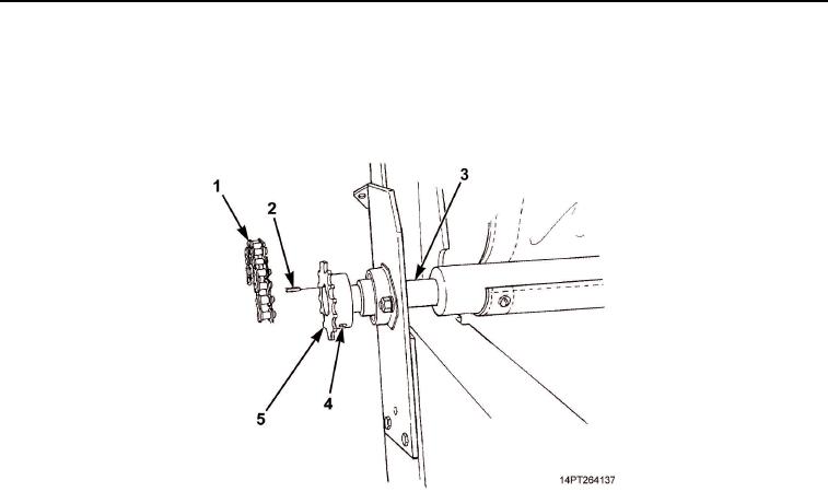
INSTALLATION
1.
Install sprocket alignment key (Figure 4, Item 2) and sprocket (Figure 4, Item 5) on roll-up bar
(Figure 4, Item 3). Tighten set screw (Figure 4, Item 4).
2.
Position chain (Figure 4, Item 1) over sprocket (Figure 4, Item 5).
Figure 4. Chain and Sprocket Installation.
03/15/2011Rel(1.10)root(maintwp)wpno(M1003226413)