
TM 5-3805-264-13&P
0056
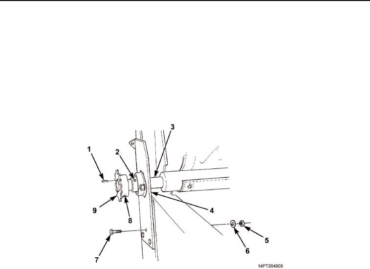
INSTALLATION
1.
Install driver's side mounting bracket (Figure 3, Item 4) on roll-up bar (Figure 3, Item 3). Position roll-up bar
on dump body and through passenger's side mounting bracket.
2.
Install three screws (Figure 3, Item 7), new lockwashers (Figure 3, Item 6), and nuts (Figure 3, Item 5) to
driver's side mounting bracket (Figure 3, Item 4) and dump body.
3.
Loosen set screw (Figure 3, Item 2) at each end of roll-up bar (Figure 3, Item 3) and center bar between
driver's side and passenger's side mounting brackets (Figure 3, Items 4 and 5). Tighten set screws.
4.
Install sprocket alignment key (Figure 3, Item 1) and sprocket (Figure 3, Item 9) on roll-up bar
(Figure 3, Item 3). Tighten set screw (Figure 3, Item 8).
Figure 3. Roll-Up Bar Installation.
5.
Install spring assembly (Figure 4, Item 7) on dump body and through welded shaft support bar and tube
(Figure 4, Item 1) with two screws (Figure 4, Item 8), new lockwashers (Figure 4, Item 9), and nuts
(Figure 4, Item 10).
6.
Connect swing arm (Figure 4, Item 5) and connecting arm (Figure 4, Item 3) with eyebolt (Figure 4, Item 4)
and new locknut (Figure 4, Item 2).
7.
Install swing arm (Figure 4, Item 5) on spring assembly shaft (Figure 4, Item 6). Install new machine key
(Figure 4, Item 11) through shaft.
8.
Install one end of rubber strap on connecting arm (Figure 4, Item 3) eyebolt and opposite end on swing arm
(Figure 4, Item 5) eyebolt.
03/15/2011Rel(1.10)root(maintwp)wpno(M1003326413)