
TM 5-3805-274-13&P
0008
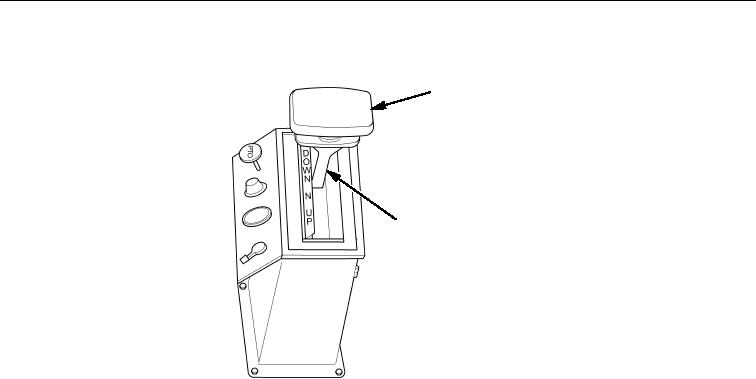
DUMPING - CONTINUED
LEVER HEAD
SHIFT LEVER
Figure 4. Hydraulic Control Lever.
6. If dump bed is to be held at a high angle for an extended period or if maintenance will be performed
with dump bed raised, install safety strut as shown in Figure 5.
a.
Raise dump bed to maximum height.
b.
Lift safety strut until it is aligned with bottom of bed as shown in Figure 5.
c.
Lower dump bed until safety strut is firmly engaged against bed cross brace.
d.
Place T-handle control lever in N (neutral) position. Refer to Figure 4.
e.
To lower dump bed, slightly raise dump bed to take weight off safety strut, swing safety strut into
stowed position, and lower.
7.
When dumping is finished, squeeze T-handle control head of hydraulic control lever and move lever to
down position as shown in Figure 4.
8.
When dump bed is fully lowered, release T-handle control and place lever in N (neutral) position as
shown in Figure 4.
9.
Disengage the PTO (TM 9-2320-273-10).
10.
Lift tailgate control lever upward as far as it will go. Slide safety loop over lever as shown in Figure 1.
11.
Check jaws on both sides of tailgate hinge. Ensure they are closed firmly over pins as shown in Figure 3.