
TM 5-3805-274-13&P
0019
Table 1. Operator Preventive Maintenance Checks and Services for M917 Dump Truck Body - Continued.
ITEM TO BE
EQUIPMENT NOT
ITEM
INTERVAL
CHECKED OR
PROCEDURE
READY/AVAILABLE
NO.
SERVICED
IF:
Control
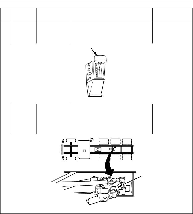
12.
During
Grip head
Ensure grip head operates smoothly and
mechanism does
(Figure 12, Item 1) control lever moves without binding.
not work properly.
1
Figure 12. Grip Handle.
Control
During
Control valve
13.
Ensure control lever returns to N (neutral)
mechanism does
(Figure 13, Item 1) from UP or DOWN position.
not work properly
or Class III leaks
are evident.
1
Figure 13. Control Valve.