
TM 5-3805-274-13&P
0034
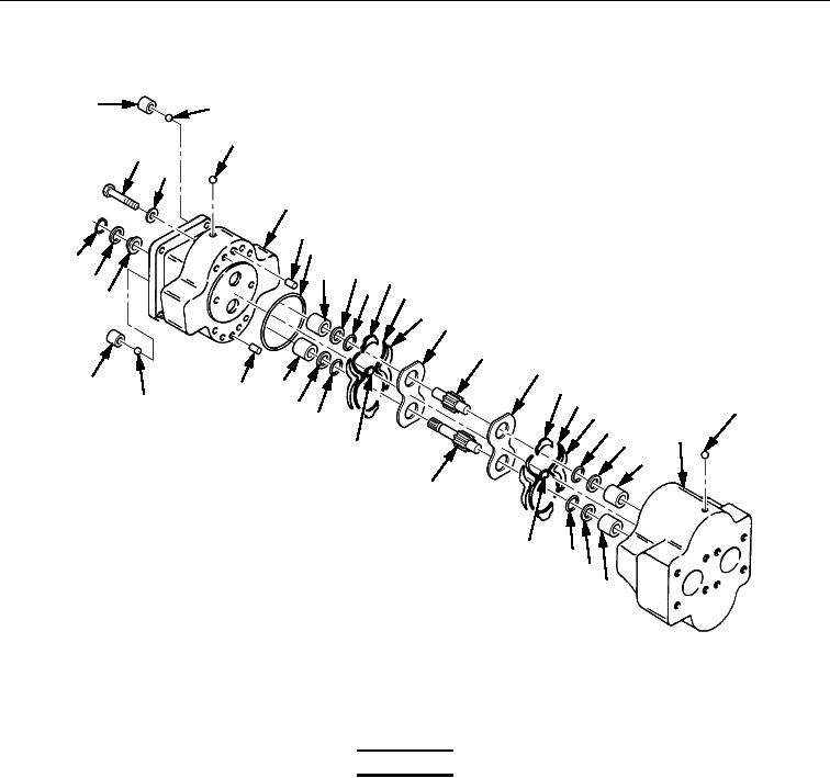
DISASSEMBLY - CONTINUED
1
2
3
30
31
4
5
6
29
8
7
10
28
9
11
27
12
13
14
15
1
16
7
5
17
2
23
8
18
9
19
22
20
26
21
25
24
19
20
21
Figure 1. Hydraulic Pump Disassembly.
END OF TASK
CLEANING AND INSPECTION
WARNING
Compressed air used for cleaning must not exceed 30 psi (207 kPa).
Use only with effective chip guarding and personal protective
equipment (goggles/faceshield, gloves, etc.). Failure to comply may
result in injury to personnel. Seek medical attention in the event of an
injury.
NOTE
Wash all parts thoroughly with clean solvent and blow dry. This
should remove any foreign matter trapped in the pump.
1. Visually inspect all parts. Gear track is inside pump body (Figure 1, Item 22). Measure depth of gear
track. If groove is deeper than 0.0050 in. (0.013 cm), body should be rejected. If track is less than
0.005 in. (0.013 cm), body may be reassembled provided it is not cracked or damaged.
2. Examine top pressure plate (Figure 1, Item 13) and bottom pressure plate (Figure 1, Item 15). If gear
track or groove is deeper than 0.005 in. (0.013 cm), replace plate.
3. Gear journals should be measured within 0.38 in. (0.96 cm) of gear. Measure diameter of journals where
shaft has run in bearings. Gears should be rejected if there is more than 0.001 in. (0.0025 cm) variation
in two measurements.