
TM 5-3805-274-13&P
0034
ASSEMBLY - CONTINUED
CAUTION
Do not oil screws. Screws and screw holes must be dry for proper
torque reading. Failure to comply may result in damage to
equipment.
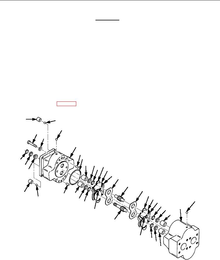
18. Wash eight screws (Figure 2, Item 30) and washers (Figure 2, Item 31) in cleaning solvent and dry.
19. Install two washers (Figure 2, Item 31) and screws (Figure 2, Item 30) in opposite holes. Torque screws
(Figure 2, Item 30) to 80 lb-ft (108 Nm).
20. Using 10 in. wrench, check if drive gear (Figure 2, Item 25) turns. Shaft will be tight, but should turn
freely with maximum of 510 lb pull.
21. If drive gear (Figure 2, Item 25) will not turn, disassemble hydraulic pump and examine for burrs or
foreign material causing buildup or interference in parts.
22. Remove foreign material and reassemble.
23. When drive gear (Figure 2, Item 25) turns properly, install washers (Figure 2, Item 31) and screws
(Figure 2, Item 30). Torque to 80 lb-ft (108 Nm).
24. Install hydraulic pump WP 0033.
1
2
3
30
31
4
5
6
29
7
8
10
28
9
11
27
12
13
14
15
1
16
7
5
17
2
23
8
18
9
19
22
20
26
21
25
24
19
20
21
Figure 2. Hydraulic Pump Assembly.
END OF TASK
END OF WORK PACKAGE
0034-5/6 blank