
TRUCK SERVICE MANUAL
FUEL SYSTEM
This check was incorporated into the ST990 as a time
Leakage Checks
and labor savings. Very little extra time is required to
check the cup to plunger seat while the injector is
The plunger to body and plunger to cup leakage check
installed in the machine for the body to plunger tests.
gives a measurement of fuel bypass between plunger
This check is preferred over the ST570 leakage check.
body and plunger cup to help determine if injector is to
Installation
be rehoned or can be calibrated and reused in an
Requirements Of ST990
engine.
The following facilities are necessary for acceptable
installation of the ST990:
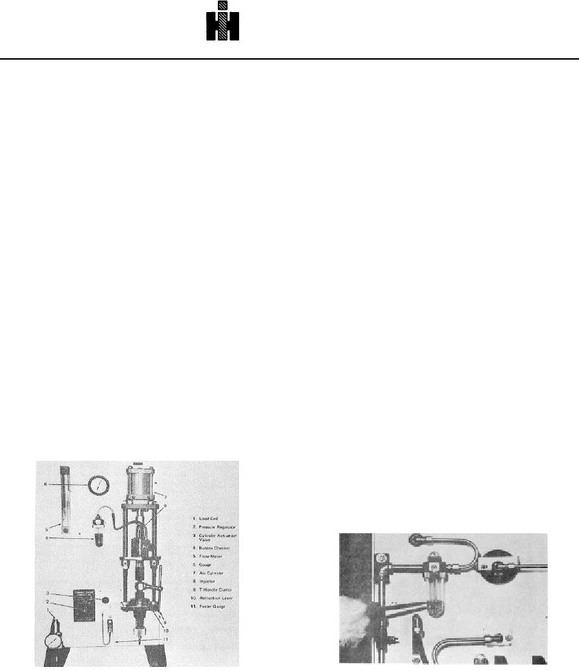
ST990 Injector Leakage Tester
1. A clean area with good lighting. An enclosed
The ST990 Injector Leakage Tester was developed and
fuel systems area is preferred. When a tightly
released in order to make available to the field a
enclosed room is used, due to the extreme
standard tool to accurately determine the degree of
sensitivity of the air flow meter, the ball float will
acceptability of used injectors. Fig. 6144.
fluxuate slightly during opening and closing of
The ST990 performs tests on all current Cummins PT
the door. Other than not being able to obtain an
injectors except L series. These tests are as follows:
accurate reading during actual swinging of the
1. Body to plunger leakage in area below the
door, such a room has no adverse effects and is
metering orifice. With the plunger retracted
desirable.
off the cup seat by approximately 0.048 inch
2. A work bench of standard height which is not
[1.22 mm], air is forced through the cup spray
subject to pounding or other heavy work. The
holes past the body to plunger clearance and is
bench must not have a vise or other shop
measured with a precision flow meter. This
equipment which is generally subject to impacts.
check supersedes the body to plunger leakage
3. An air supply of 80 psi [552 kPa] minimum
test on the ST790, In which injector delivery with
pressure. The air line to the ST990 should not
a 0.
inch [1.3 97 mm] restrictor orifice is
be in a location where intermittent pressure
compared to delivery with the standard 0.011,
drops are caused by actuation of other shop air
0.013 or 0.020 inch [.28, .33 or .51 mm] orifices
equipment.
(depending upon injector model).
Assembly And Installation Of ST990
2. Cuptoplunger seat. The plunger is seated in the
1. Mount rubber isolation pads to feet with
cup with 200 lbs. [90.72 kg] load. Any leakage
capscrews provided.
is measured in bubbles which are released
2. Mount feet to panel.
When feettopanel
under a fluid. level.
capscrews are snug, panel must be installed in a
vertical position to insure proper operation of air
flow meter.
3. Fill air cylinder oiler 1/3 to 1/2 full of injector test
oil. Fig. 6145. Make sure sealing ring is in place
before tightening bowl retainer.
Fig. 6-1-45, F60168. Air cylinder oiler oil level
Fig. 6-1-44, F60167. ST990 injector leakage tester
465

