
TRUCK SERVICE MANUAL
FUEL SYSTEM
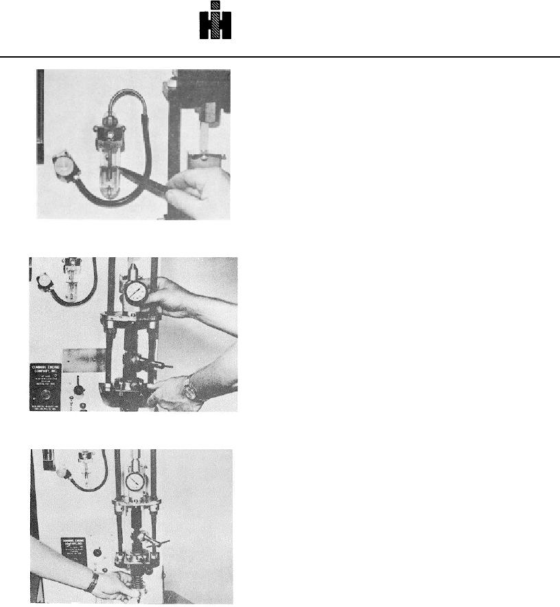
4. Fill bubble checker bowl with injector test oil to oil
level marker. Fig. 6-1-46. To more easily fill bowl to
specified level, it may be filled approximately 3/4 full and
then drained to proper level through valve at bottom of
bowl.
5. Use a vise-grip wrench while connecting air supply
line to prevent disturbance to threads.
6. Install T-handle clamping mechanism backed out
approximately 1/2 thread turn from snug position.
7. Install retraction handle and lock into position with
jam.
8. Set pressure regulator at 60 psi [414 kPa].
9. Operate air cylinder a few times and set final pressure
at precisely 60 psi [414 kPa]. The air pressure must be
held at 60 psi [414 kPa] during all tests.
Fig. 6-1-46, F60169. Bubble check or bowl oil level
10. The velocity of air cylinder piston rod may be
adjusted as desired with small valve at rear of panel.
Loosen locknut and screw valve stem in to decrease
piston speed or back screw out to increase piston speed.
Lock the nut on the stem when desired piston speed is
attained.
11. With retraction lever in "A" position, install load cell
and clamp into position. Fig. 6147.
12. Adjust knurled knob until load cell reads 200 psi
[1379 kPa]. Fig. 6148. The psi [kPa] reading on load
cell is a direct reading in pounds [kg] load, since load
cell piston area equals 1 square inch [6.45 sq cm].
Adjust knurled a knob to obtain 200 lbs [90.7 kg) load
during several clamping cycles.
13. With load cell clamped at 200 lbs. [90.7 kg) load,
use the feeler gauge to adjust locknuts into position and
Fig. 6-1-47, F60170. Installing ST-990 load cell
tighten. Clamping mechanism should be checked daily
with load cell and locknuts adjusted If necessary. Do not
adjust locknuts unless load cell is used.
ST-990
Plunger-To-Barrel
And
Plunger-To-Cup Check
PT (type D) Injector
1.
Remove ST10583 locating screw from
Service Tool 3375086 or ST1058 Adapter Pot
Assembly. Oil injector "0" rings. Install ST1089
Plunger Extension on plunger. Remove spring.
2.
Align injector delivery orifice with locating screw
hole or burnishing hole in adapter pot.
3.
Using hand pressure, ST1298 or 3375084, press
injector into pot until it bottoms. Fig. 6156.
Fig. 6-1-48, F60171. Adjusting load cell pressure
4.
Insert and tighten locating screw.
Note:
When testing Service Tool
3375089 or ST10586 Spacer must be
used.
466

