
TRUCK SERVICE MANUAL
BRAKES-AIR
REASSEMBLY
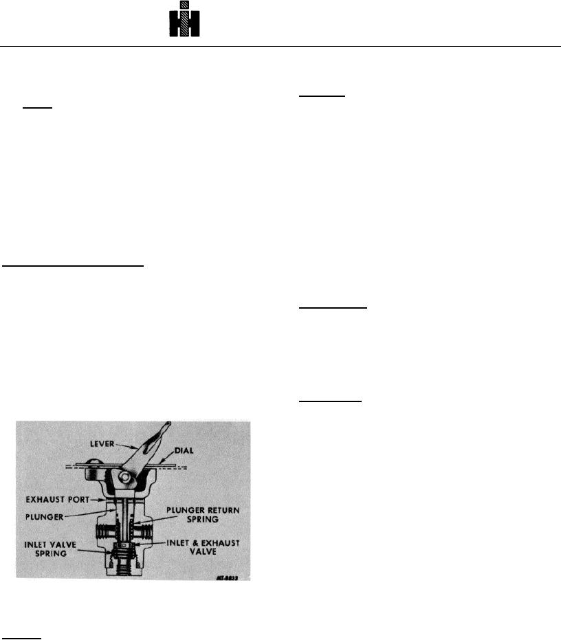
the device being operated.
Lubricate O-rings, O-ring sealing surfaces and stem
Releasing
When the lever is released, the plunger is raised by
with Item 3 of LUBRICANT SPECIFICATIONS (refer to
Fig. 4 for numbers in parenthesis).
the plunger spring and the inlet valve moves to its seat
and is held closed by the inlet valve spring and inlet air
pressure. Any air pressure in line or lines connecting the
1. Install new O-rings on stem (10) and piston (5).
two-way valve with the device being operated will be
2. Insert stem in valve body; then position piston (5)
exhausted through the hollow plunger and exhaust
in valve body over stem.
opening near the top of the valve.
3. Install stem nut (3).
MAINTENANCE
4. Install valve end cap (1) and new gasket (2).
Once each year or every 100, 000 miles the two-way
Before vehicle is returned to service, perform
valve should be disassembled and thoroughly cleaned.
SERVICE CHECKS on valve as outlined.
Replace all grommets and inlet valves worn or damaged
in any way.
TWO-WAY CONTROL VALVE
(BENDIX-WESTINGHOUSE TYPE TW-1)
SERVICE CHECKS
DESCRIPTION
Operation Test
Plug one delivery port and install an air pressure test
The TW-1 two-way control valve, which is an off-on
gauge in remaining port. Install second air pressure
valve, is mounted on the instrument panel and is
gauge in the air inlet line. With air connected to the inlet
primarily used in conjunction with various other air
port, place the lever in applied position. The air gauge in
devices in vehicle air systems. The systems in which
the delivery port should read the same as the gauge
these valves may be used are: transmission air control
installed in air inlet line.
valve, quick release valve, two-speed shift cylinders,
manually operated tractor protection valve and power
Leakage Test
divider lock-out system.
With air supplied to the inlet port of the two-way
valve and the lever in released position, use Leak
Detector Tester (SE-2326) at exhaust opening at top of
the valve (where lever enters valve) to locate any leak.
Move lever or button to applied position and check
exhaust opening with Leak Detector Tester (SE-2326) to
locate leakage past exhaust plunger.
REMOVE
1. Disconnect air lines at two-way valve.
2. Remove machine screws securing control valve
in place and remove valve.
INSTALL
1. Install valve using the machine screws. Position
Fig. 5 Lever-Operated Two-Way Control Valve
lever-operated or push button-operated two-way
valve on instrument panel with body of valve
OPERATION
behind instrument panel and dial or instrument
panel plate showing on front of panel.
Applying
When the lever is actuated in the delivery position,
2. Connect all air lines and perform tests outlined in
the hollow plunger of the valve is depressed and makes
SERVICE CHECKS.
contact with the inlet valve and unseats it. In this
position the exhaust passage through the hollow plunger
is closed and air from the inlet port has free passage
through the two-way valve and out the delivery port to
162