TRUCK SERVICE MANUAL
BRAKES-AIR
ASSEMBLE
A. Clean all parts thoroughly and inspect. Check
angled faces of wedge to see that they are free from
pits or marks. If "E" washer type lock is used,
inspect wedge shaft lock groove to see that it is
sharp and clean. Inspect roller retainer cage to
make sure it will contain rollers properly and inspect
the spring for marks that would cause breakage.
Replace parts if necessary.
B.
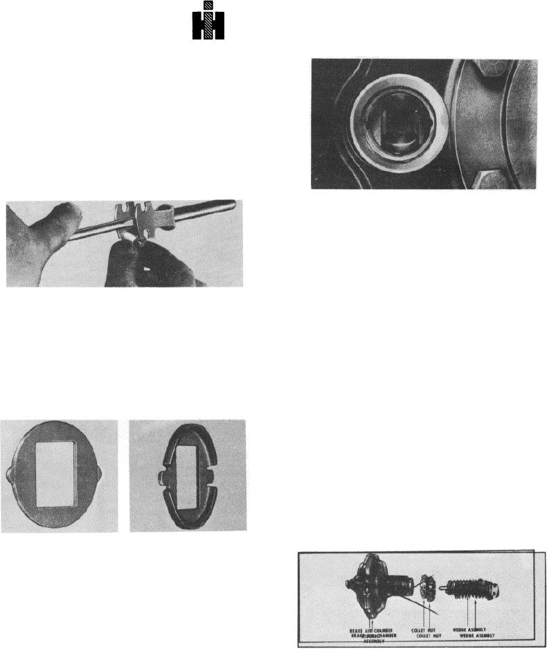
Insert wedge shaft into roller retainer cage so
angled faces of the wedge head are exposed.
These tabs serve to align the wedge assembly as it is
installed into the plunger housing by engaging grooves in
the wedge bore. If the plunger housing is not equipped
with such grooves, remove the tabs at the breakoff
marks and file the O.D. of the retainer smooth.
E
Install wedge spring over wedge shaft, large coil
diameter first. Add spring washer and compress
spring by hand far enough to expose cotter key hole
C.
Insert a thin bladed screwdriver between flat of the
or "E" lock groove and install lock (cotter key or "E"
wedge head and roller retainer cage. Spread cage
washer).
open just far enough to insert roller (journal hub into
cage slot). Tip roller into cage and position other
F. Install the wedge assembly into the plunger housing.
journal hub into slot of retainer. Install other roller in
Check for correct roller-plunger engagement by (1)
same manner and remove screwdriver. DO NOT
pushing on wedge rod by hand while checking for
force rollers thru ends of the cage slots.
plunger and shoe lift, and (2) measuring the standout
of the wedge rod from the end of the threaded
D. Install spring retainer over wedge shaft and position
housing bore. When properly assembled, the wedge
centrally over cage and roller assembly. Install rub-
standout is 2 1/4
ber boot when used.
INSTALLING POWER UNIT ONTO
BRAKE ASSEMBLY
A. Check position of the wedge in plunger housing to
make certain wedge assembly is properly seated.
Be sure to replace automatic adjusting identification
ring (if used) on power unit tube. Thread spanner
nut or collet nut onto power unit tube and install
spanner nut retainer if used. Apply a non-hardening
1 1/2" ASSEMBLY
1 3/4" ASSEMBLY
sealer to the first three threads of the chamber tube.
NOTE: Current production and service replacement use
a spring retainer that has two tabs or protrusions on the
O.D.
This is the correct position of the collet nut when used
with current brake spider having a conical counterbore.
207

