
TRUCK SERVICE MANUAL
ENGINE
2. Use light finger pressure at rocker lever contact
surface (1) to hold crosshead in contact with valve stem
(2) (without adjusting screw).
3. Turn down crosshead adjusting screw until it touches
valve stem (3).
4. With new crossheads and guides,-advance setscrew
an additional one-third of one hex (20 deg.) to straighten
stem on its guide (5) and compensate for slack in
threads. With worn crossheads and guides, it may be
necessary to advance screw as much as 30 deg. to
straighten stem on Its guide.
5. Using ST-669 Torque Wrench Adapter, tighten
locknuts to 22 to 26 ft-lbs [30 to 35 Nml. If ST-669 is
not available, hold screws with screwdriver and tighten
locknuts to 25 to 30 ft-lbs [34 to 41 Nm]
Fig. 2-53 (N-11466)
6. Check clearance (6) between crosshead and valve
Table 2-14: Injector Adjustment (Oil Temperature)
spring retainer with wire gauge. There must be a
minimum of 0.025 inch [0.64 mm] clearance at this point.
Cold Set
Hot Set
Valve Adjustment
Cast Iron Rocker Housing
The same engine position used in adjusting injectors is
48 inch-lb
72 inch-lb
used for setting intake and exhaust valves.
[5.4 N m]
[8.1 Nm]
Aluminum Rocker Housing
1. While adjusting valves, make sure that the
72 Inch-lb
72 inch-lb
compression release, on those engines so equipped, is
18.1 No m]
[8.1 Nm]
in running position.
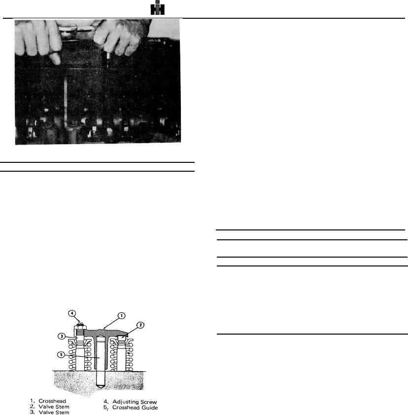
Crosshead Adjustment
Table 2-15: Valve Clearance - Inch [mm]
Crossheads are used to operate two valves with one
rocker lever. The crosshead adjustment is provided to
Intake Valves
Exhaust, Valves
assure equal operation of each pair of valves.
The crosshead adjustment changes as a result of valve
Cold Set
Hot Set
Cold Set
Hot Set
seat wear during engine operation.
Make sure
Aluminum Rocker Housing
crossheads are adjusted before adjusting valve rocker
0.014
0.014
0.027
0.027
1. Loosen valve crosshead adjusting screw locknut and
[0.36]
[0.36]
[0.69]
[0.69]
back off screw (4, Fig. 2-54) one turn.
Cast Iron Rocker Housing
0.016
0.014
0.029
0.027
(0.411
[0.361
(0.74]
[0.691
2.
Loosen locknut and back off the
adjusting screw. Insert feeler gauge between rocker
lever and crosshead. Turn the screw down until the lever
just touches the gauge and lock the adjusting screw in
this position with the locknut. Fig. 2-55. Tighten locknut
to 40 to 45 ft-lbs [54 to 61 No m] torque. When using
ST-669 torque to 30 to 35 ft-lbs [41 to 47 NM].
3. Always make final valve adjustment at stabilized
engine lubricating oil temperature. See Table 2-15 for
appropriate valve clearances.
Fig. 2-54,(N21461) Valve crosshead.
299