ENGINE
TRUCK SERVICE MANUAL
Definition of "Cold Set"
Injector And Valve Adjustment
Engine must have reached a stabilized temperature (oil
Note: Injectors and valves may be adjusted without
temperature to be within 10 deg. F of ambient air
removal of the Jacobs Brake by using 3375096 Jacobs
temperature).
Brake Kit. This kit includes a special rocker lever
Definition of "Hot Set"
actuator, dial indicator extension, feeler gauge and
1. Set injectors and valves immediately after the engine
special offset wrenches.
has reached normal stabilized operating oil temperature.
See Table 2-12 for adjustment with cast iron or
aluminum rocker housings.
2. If oil temperature gauge is unavailable, set injectors
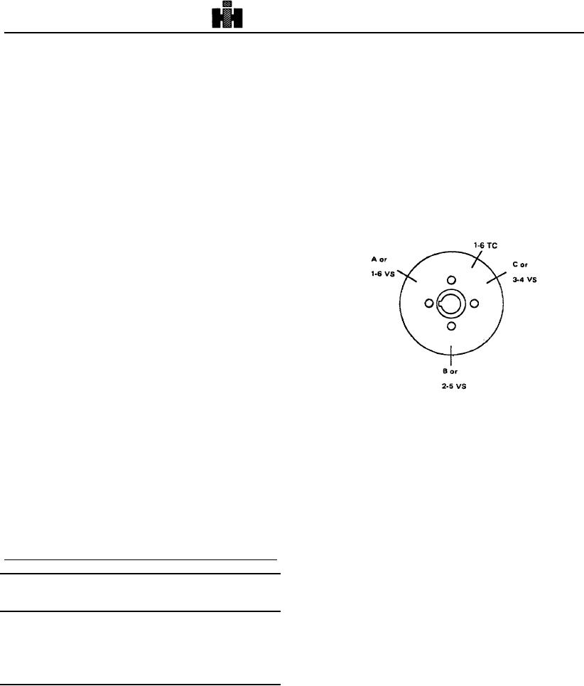
1. Bar engine until A or "1-6 VS" is aligned with pointer.
and valves immediately after engine has operated at
Fig. 2-50. Both valve rocker levers for No. 5 cylinder
rated speed and load or at high idle for a period of 20
should be free (valves closed). Injector plunger for No.
minutes.
3 cylinder must be at top of travel. If not, check No. 2
cylinder for valves being free and No. 4 injector plunger
should be at top of travel. See Table 2-11 for Valve
Injector And Valve Adjustment Using ST-1270 Dial
Injector Set Position.
Indicator Method NH-NT Series
This method involves adjusting injector plunger travel
with an accurate dial indicator rather than tightening the
adjusting screw to a specified torque. A check can be
made of the adjustment without disturbing the locknut or
screw setting. The valves can also be checked or set
while adjusting the injectors by this method. See Table
2-11.
When engine has been set in proper position for injector
to be adjusted, tighten adjusting screw until all lash is
removed from injector train. Then tighten adjusting
screw one additional turn to properly seat links and to
squeeze oil from socket surfaces. Back adjusting screw
off until spring washer contacts stop. Now adjust zero
clearance, use 3375232 Torque Wrench and tighten
Fig. 2-50, (Nl14230) Accessory drive pulley markings
screw to 5 to 6 inch-lbs [0.56 to 0.68 N. m] torque. Zero
clearance being defined as the condition where the link is
2. Install ST-1270 to rocker housing with indicator
slightly loaded.
extension on top of injector plunger for cylinder as
Note: If torque wrench is not available, zero clearance
determined in Step 1 above. See Fig. 2-51.
can be set at point approximately where link is slightly
3. Screw injector lever adjusting screw down until
loaded, but just free enough to be rotated by thumb and
plunger is bottomed in cup, back off approximately 1/2
forefinger.
turn then bottom again, set dial indicator at zero (0).
Hold adjusting screw with screwdriver and tighten locknut
to proper torque.
Note: Care must be taken to assure injector plunger is
correctly bottomed in cup, without overtightening
Note:
If injectors were removed for cleaning or
adjusting screw, before setting dial indicator.
replacement tighten injector, hold-down capscrews In
4. Back adjusting screw out until a reading of 0.170
alternate steps' to 10 to 12 ft-lb [14 to 16 Nm J torque.
inch [4.32 mm] or 0.175 inch [4.45 mm] , reference Table
Table 2-11: Injector and Valve Set Position
2-12, is obtained on dial indicator. Snug tighten locknut.
Bar in
Pulley
Set Cylinder
5. Using ST-1193 Rocker Lever Actuator, bottom
injector plunger, check zero (0) setting. Fig. 2-51. Allow
Direction
Position
Injector
Valve
plunger to rise slowly, indicator must show plunger travel
Start
A or 1-6VS
3
5
to be within range specified in Table 2-12.
Adv To
B or 2-5 VS
6
3
6. Using ST-669 Torque Wrench Adapter to hold
Adv To
C or 3-4 VS
2
6
adjusting screw in position, torque locknut 30 to 35 ft-lb
Adv To
A or 1-6 VS
4
2
[41 to 47 No mi. If torque wrench adapter is not used,
Adv To
B or 2-5 VS
1
4
hold adjusting screw with a screwdriver, torque locknuts
Adv To
C or 3-4 VS
5
1
40 to 45 ft-lb [54
to 61 No mi.
297

