
ENGINE
TRUCK SERVICE MANUAL
"C" MAINTENANCE CHECKS
At each "C" Maintenance Check, first perform ail "A" and
"B" Checks in addition to those following.
Steam Clean Engine
Steam is the most satisfactory method of cleaning a dirty
engine or piece of equipment. If steam is not available,
use an approved solvent to wash the engine.
All electrical components and wiring should be protected
from the full force of the cleaner spray nozzle.
Check Alternator And Cranking Motor Brushes And
Commutators Failure of an alternator or cranking motor
may cause unit downtime and nearly always result in
expensive replacement.
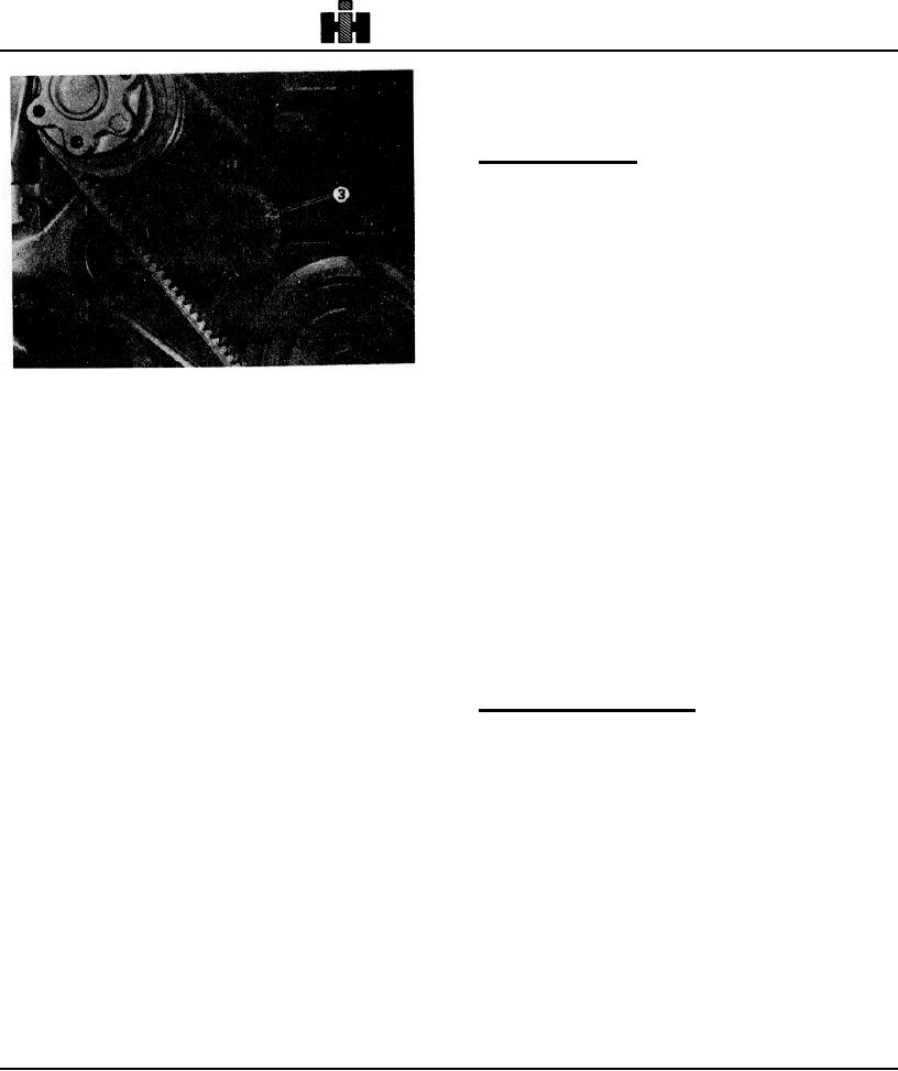
Fig. 2-29, (N11974) Water pump -with idler
1. Inspect terminals for corrosion and loose
3. Secure idler pulley or bracket in position by
connections and wiring for frayed insulation. Check
tightening locknut or capscrews and lockwashers to 45 to
mounting bolts for tightness and check belt for
55 ft-lb 161 to 75 No m] torque.
alignment, proper tension and wear.
2. Slip rings and brushes can be inspected through
Fan Drive Belts
alternator end frame assembly. If slip rings are dirty,
1. Loosen large locking nut on fan hub shaft or
they should be cleaned with 400-grain or finer polishing
capscrews securing fan hub shaft to mounting bracket.
cloth.
The fan hub will fall out of line when this is done.
Note: Never use emery cloth to clean clip rings. Hold
2. Turn the adjusting screw to increase belt tension.
polishing cloth against slip rings while rotating alternator,
3. Tighten the locknut or capscrews until the fan hub is
blow away all dust after cleaning operation.
straight. Snug the nut to maintain hub in proper
3. Check alternator bearings for wear. Shaft will be
alignment with the fan hub bracket.
excessively loose if bearings are worn.
4. If brushes are worn close to the holder, the alternator
Caution: Do not adjust to full tension with the
must be removed and sent to manufacturer's rebuild
adjusting screw, this would result in overtightening.
station.
4. Belt tension should read as indicated in Table 2-2 on
applicable gauge. If a gauge is not available, the belt
Adjust Injectors And Valves
should be checked with finger pressure at the center of
It is essential injectors and valves be in correct
the longest span. Deflection should be one thickness
adjustment at all times for engine to operate properly.
per foot [0.3 ml of pulley center distance.
One controls engine breathing; the other controls fuel
5. Tighten 855 Series Engines locknut to 400 to 450 ft-
delivery to the cylinders.
lb [542 to 610 N J, then back off 1/2 turn.
Final operating adjustments must be made using correct
6. Recheck belt tension.
values as stated.
7. Back out adjusting screw one-half turn to prevent
breakage.
Temperature Settings
Generator/Alternator Belts
The following temperature conditions provide the
Belt tension should be as indicated in Table 2-2
necessary stabilization of engine components to assure
Readjusting New Belts
accurate settings.
All new belts will loosen after running a short period of
time and must be readjusted to installation tension. After
initial installation and retensioning, belts should then be
set at running tension. Ref. Table 2-2.
296