
ENGINE
TRUCK SERVICE MANUAL
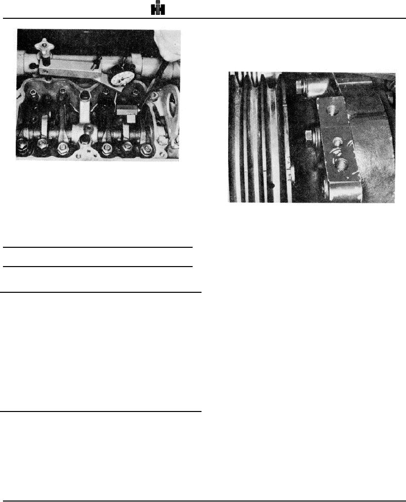
2. Bar engine in direction of rotation until a valve set
mark (1, Fig. 2-52) aligns with the boss (2) on the gear
case cover. Example: A or "1-6 VS". This location is
marked with a notch in the drive pulley. Note: Fig. 2-52
illustrates 3-4 "VS" valve set mark,
Fig. 2-51, (N114237) Bottoming injector plunger in cup
7. Actuate injector plunger several times as a check of
adjustment. Remove dial indicator assembly.
8. Adjust valves on appropriate cylinder as determined
Fig. 2-52, (N114220) Valve set timing marks
in Step 1 and Tables 2-11 and 2-12. Tighten locknuts
same as injector locknut.
3. Check the valve rocker levers on the two cylinders
9 Continue to adjust remaining cylinders. See Table 2-
aligned as indicated on pulley (example: 1 and 6
11.
cylinders for A or "1-6 VS"). On one cylinder of the pair,
both rocker levers will be free and valves closed, this is
Table 2-12: Adjustment Limits Using Dial Indicator
cylinder to be adjusted.
Method Inch [mm]
4. Adjust injector plunger first, then crossheads and
Oil
Injector
Valve Clearance
valves to clearances indicated in the following
Plunger
paragraphs.
Temp
Travel
Intake
5. Engine Firing Order is 1-5-3-6-2-4.
Aluminum Rocker Housing
6. Continue to bar engine to next "VS" marks and
adjust each cylinder in firing order.
Cold
0.170 + 0.001
0.011
0.023
Note: Only one cylinder is aligned at each mark. Two
(4.32 + 0.03]
[0.28]
[0.58]
complete revolutions of the crankshaft are required to
Hot
0.170 + 0.001
0.008
0.023
adjust all cylinders.
[4.32 + 0.03]
[0.20]
[0.58]
Cast Iron Rocker Housing
Injector Plunger Adjustment
The injector plungers must be adjusted with an Inch-
pound torque wrench to a definite torque setting. A
Cold
0.175 + 0.001
0.011
0.023
torque wrench with a screwdriver adapter can be used
[4.45 + 0.031
[0.28]
[0.58]
for this adjustment. See Fig. 2-53.
Hot
0.175+ 0.001
0.008
0.023
1. Turn adjusting screw down until plunger contacts cup
[4.45 + 0.03]
[0.20]
[0.58]
and advance an additional 15 degrees to squeeze oil
from cup.
Adjust Injectors And Valves NH, NT (Torque Method)
2. Loosen adjusting screw one turn; then, using a
torque wrench calibrated in inch-pounds and a
Timing Mark Alignment
screwdriver adapter, tighten' the adjusting screw to
1. Loosen the injector rocker lever adjusting nut on all
values shown in Table 2-14 and tighten the locknut to 40
cylinders.
This will aid In distinguishing between
to 45 ft-lb [54 to 61 Nm] torque. If ST-669 Torque
cylinders adjusted and not adjusted.
Wrench Adapter is used, torque to 30 to 35 ft-lb [41 to 47
Nm.
298