
STEERING
TRUCK SERVICE MANUAL
7.
Carefully slide the actuating valve into the piston
so that the slot on the end of the valve is
positioned over the pin.
8.
Position the remaining reversing spring on
shoulder of the valve end.
9.
Reinstall valve adjusting nut, turning it clockwise
into the piston until it is against the spring. Align
the reference marks on the nut and piston. Then
lock nut in place by installing the locking pin. Be
sure pin is below the outside edge of piston.
10.
Install piston rings. NOTE: If piston rings are
tapered on one side, install the taper outward to the
piston end. if rings are marked "top" on one side, also
assemble these rings with the marked side outward to
the piston end. Rings which are neither marked nor
tapered are not required to be installed on the piston in
Fig . 31
any special manner.
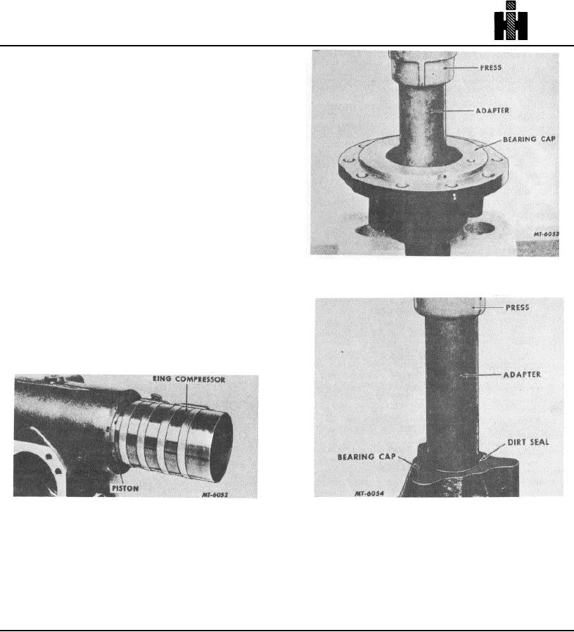
11.
Install piston assembly using a ring compressor
on each end. Fig. 30 illustrates ring compressor on
second ring. Be sure piston is installed with the
actuating shaft opening facing the bearing cap end.
NOTE: Before installing piston, coat piston and cylinder
walls with oil.
Fig . 32
Fig . 30
12.
Using a new gasket reinstall the cylinder head.
The alignment marks will aid in reinstalling the
head in the correct position. The opening for the
plunger must be in alignment with relief valve in
the piston. Check torque chart for bolt tightening,
643