TRUCK SERVICE MANUAL
STEERING
13.
Press a new oil seal and dirt seal into bearing
cap, Figs. 31 and 32.
Lubricate surface between seals before
installing actuating shaft assembly.
(Use Ball Bearing Lubricant.)
14.
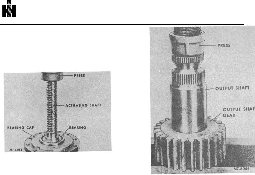
Press actuating shaft assembly into the bearing
cap, Fig. 33.
Fig .
33
15.
Install bearing retaining nut. Insert locking pin
through the hole in bearing cap and into the
hole in nut. If a new nut is being used, drill a
Fig .
34
3/32" hole in nut. The nut must be in place to
drill this hole. Drill through the locking pin hole
18
Insert output shaft in gear housing aligning mark
in the bearing cap and 3/16" into the nut.
on the center tooth on the pinion with mark on
the output shaft. NOTE: Be very careful so that
16.
Using a new gasket on the bearing cap thread
the gear tooth and rack tooth are properly
actuating shaft into the valve. Line up punch
aligned. If a tooth on the pinion strikes the
marks on gear housing and bearing cap. Turn
ground outside diameter' surface of the piston, a
shaft until cap comes into place on the end of
burr will be raised which will score the cylinder
cylinder. Check plunger hole alignment with
wall. This burr should be removed with a fine
valve seat in the piston. Tighten bolts to
hand stone before further assembly.
specified torque.
19.
Install the gear retaining nut. The nut must be
17.
Align the timing mark on output shaft gear with
tight against the output shaft gear.
The
marked spline on the output shaft and
capscrews are then installed in the retaining nut.
reassemble. Use a press if necessary, Fig. 34.
If the holes do not line up with the gear, back the
nut off until they do. Tighten the capscrews with
an Allen wrench.
644

