TRUCK SERVICE MANUAL
TRANSMISSION
INSPECTION AND REBUILD
Para 6-10
(8) Install support assembly 16 and snapring 19
into the valve bore.
(9) Place converter housing 16 (A, foldout 8) on
the work table, front side down.
(10) Place front support gasket 17 onto the
converter housing. Aline holes in the gasket with those
in the converter housing.
(11) Install front support assembly I (B, foldout 10)
onto converter housing 16 (B, foldout 8).
(12) Install three 3/8-16 x 2 1/2-inch bolts into the
front support (fig. 6-13). Tighten the bolts to 36 to 43
pound feet (49 to 58 Nm) torque.
(13) Install one 3/8-16 x 1 1/2-inch bolt into the hole
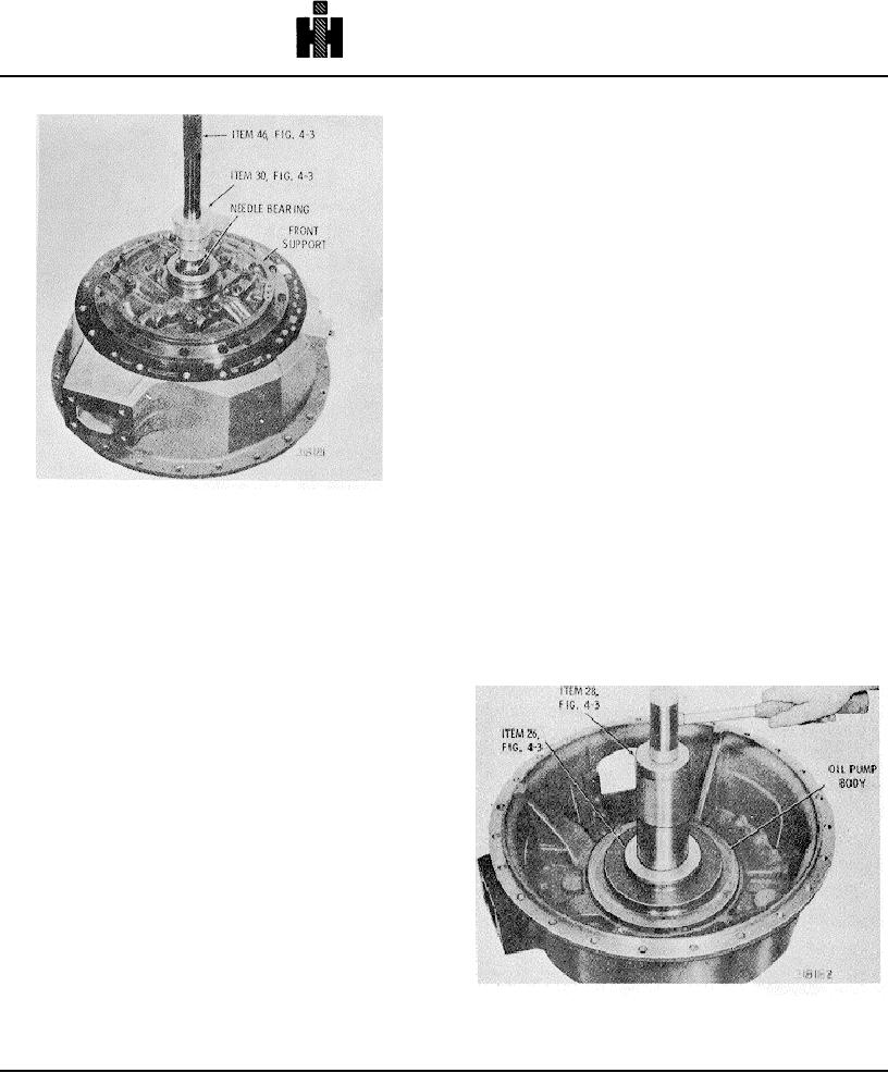
Fig. 6-17. Tool for installing front support needle
between the two valve bores that are closer to each
bearing.
other (fig. 6-13). Tighten it to 36 to 43 pound feet (49 to
58 Nm) torque.
(4) Install spring 4 and valve stop 5. Place washer
6 on spring 4 and compress the spring into the valve
bore until the snapring groove is clear (fig. 6-16). Install
(14) Install fifteen 3/8-16x 11/2-inch bolts into the
snapring 7.
outer bolt circle of the front support (fig. 6-13). Tighten
the bolts to 36 to 43 pound feet (49 to 58 Nm) torque.
(5) Install lockup shift valve 8, small end first, into
the bore indicated in B, foldout 10. Be sure the valve will
move freely of its own weight in its bore.
(6) Install spring 9 and valve stop 10. Place
washer 11 on spring 9 and compress the spring into the
valve bore until the snapring groove is clear (use spring
compressor). Install snapring 12.
(7) Install spring 13 into the converter regulator
valve bore indicated in B, foldout 10. Install converter
bypass valve 14 and valve seat 15. Spring compressor
is not required for this spring.
748

