
TRUCK SERVICE MANUAL
TRANSMISSION
Para 6-10
HT 700D SERIES TRANSMISS IONS
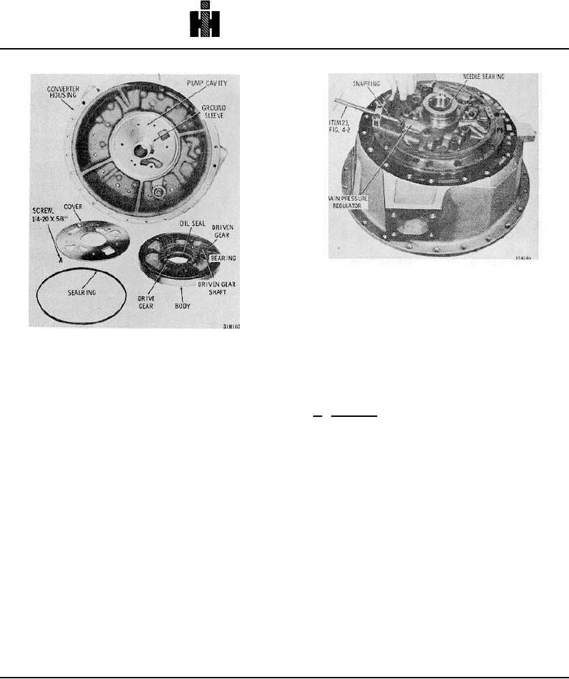
Fig. 6-16. Removing (or installing) main pressure
regulator snapring.
(13) Do not remove the ground sleeve (fig. 6-15)
from the front support. If there is evidence of movement,
or damage, replace front support and ground sleeve
assembly 2 (B, foldout 10).
Fig. 6-15. Oil pump and torque converter housing .
NOTE
(7) Remove the spring compressor, and remove
Refer to paragraph 6-2, above.
washer 6 (B, foldout 10), valve stop 5, spring 4, and main
pressure regulator valve 3.
b. Assembly (A, foldout 8).
(8) Using the spring compressor, remove snapring
12, washer 11, valve stop 10, spring 9, and lockup shift
(1) If the needle bearing was removed from the
valve 8.
front support (fig. 6-17), install a new bearing. Installer
30 (fig. 4-3) may be used with handle 46 for driving the
(9) The spring compressor is not required for the
bearing, or without the handle when press-installing the
remaining valve components. Push inward against valve
bearing.
support assembly 16, and remove snapring 19. Remove
support assembly 16, seat 15, converter bypass valve
NOTE
14, and spring 13.
(10) Remove the 19 bolts remaining in the front
When no installer is available, the depth of
support assembly (fig. 6-13). Lift off the front support
installation must be measured. Proper depth,
assembly and gasket.
from rear of hub to rear of bearing is 1.26 to 1.28
(11) If replacement is necessary, remove the
inches (32-32.5 mm)
needle bearing from the bore of the support hub (fig. 6-
(2) Install the main-pressure regulator and lockup
16).
shift valves, as described in (3) through (6), below.
(12) If parts replacement is necessary, remove test
Install the converter regulator valve, as described in (7)
plugs 18 (A, foldout 8) from housing 16.
through (9), below.
(3) Install main-pressure regulator valve 3, small
end first, into the bore indicated in B, foldout 10. Be sure
the valve will move freely of its own weight in its bore.
747