
TRUCK SERVICE MANUAL
TRANSMISSION
INSPECTION AND REBUILD
Para 6-6/6-8
6-8. TORQUE CONVERTER STATOR ASSEMBLY
(3) While holding inward against adjusting ring 15,
remove retainer pin 6. Relieve the spring pressure.
a. Disassembly (B, foldout 7)
(4) Remove adjusting ring 15, washer 14, valve
stop 13, spring 12, and valve ll.
(1) Rotate stator freewheel roller race 14 in a
clockwise direction so the race may be removed.
(5) Remove retainer pin 4 and plug valve 16.
(2) Remove race 14, thrust bearing 13, thrust
NOTE
bearing race 12, ten stator rollers 11 and ten freewheel
Refer to paragraph 6-2, above.
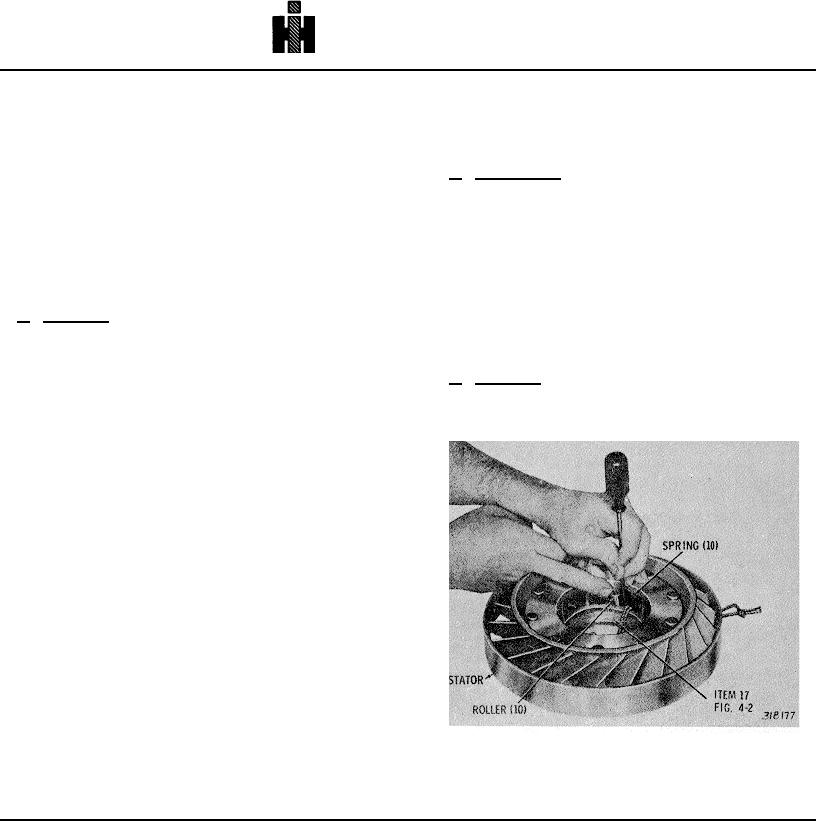
roller springs 10 from stator 9.
NOTE
b. Assembly (A, foldout 17)
(1) Install, plug valve 16, and retainer pin 4.
Refer to paragraph 6-2, above.
NOTE
b. Assembly (B, foldout 7)
(1) Place stator 9 on the work table, rear upward,
Valves, when installed dry, should move by their
and install thrust bearing race 12 into the stator.
own weight.
(2) Install valve 11 into valve body 3.
(3) Install spring 12, valve stop 13, washer 14, and
adjusting ring 15. Aline the hole in valve stop 13 with the
pin hole in valve body 3. Position adjusting ring 15 as
before removal.
(4) Press inward against adjusting ring 15 until
retainer pin 6 can be installed.
(5) Install relay valve 7, spring 8, valve stop 9.
NOTE
In earlier models, valve stop 9 consisted of two
separate pieces.
(6) Press inward against valve stop 9, and install
retainer pin 5.
Fig. 6-9. Installing stator freewheel roller
744