
TRUCK SERVICE MANUAL
TRANSMISSION
Para 6-4
HT 700D SERIES
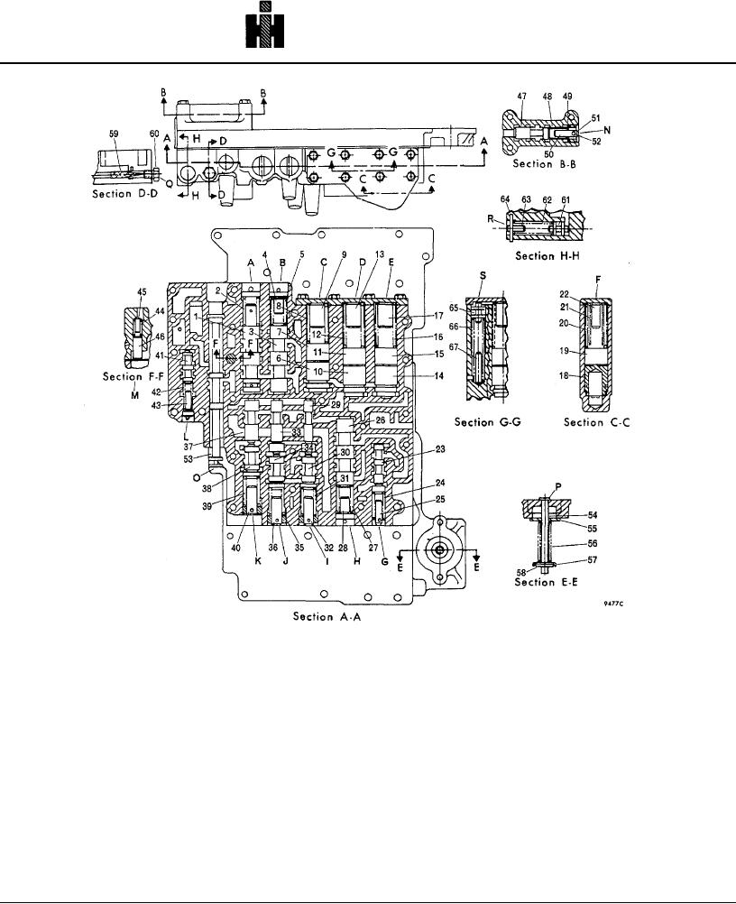
Fig. 6-7. Control valve assembly - with components installed.
follows. Compress cup washer 4 (B, foldout 16) and
(7) Disassemble the modulator valve body, removed
remove pin 5. Release washer 4 and remove it.
in (3), above. Press adjusting ring 22 inward and
Remove spring 3 and valve 2. Remove lubrication valve
remove retainer pin 16. Release the adjusting ring and
pin 6 from the oil transfer plate.
remove it. Remove valve stop 21, washer 20, spring 19,
and valve 18.
NOTE
(8) Remove priority valve 46 (fig. 6-7) spring 44, and
Before the modulator valve is disassembled (in
valve stop 45 from the control valve assembly.
(7), below), the grooves in adjusting ring 22 in
which retainer pin 16 seats must be marked to
(9) Position valve body 24 (B, foldout 16), flat side
insure correct reassembly. Adjusting ring 22
downward, on the work table. Remove plug 58 and
also must be identified for installation into the
screen assembly 59.
same bore from which removed.
739