
TRUCK SERVICE MANUAL
TRANSMISSION
Para 6-1/6-3
Section 6. INSPECTION AND REBUILD OF SUBASSEMBLIES
6-1. SCOPE OF SECTION 6
This section describes the disassembly and assembly of
subassemblies that were removed in Section 5. For
rebuild procedures, refer to the exploded views (foldouts
7 through 17) located at the end of this manual.
Reference is also made to line drawings and
photographs in this section.
6-2. GENERAL INFORMATION FOR SUBASSEMBLY
REBUILD
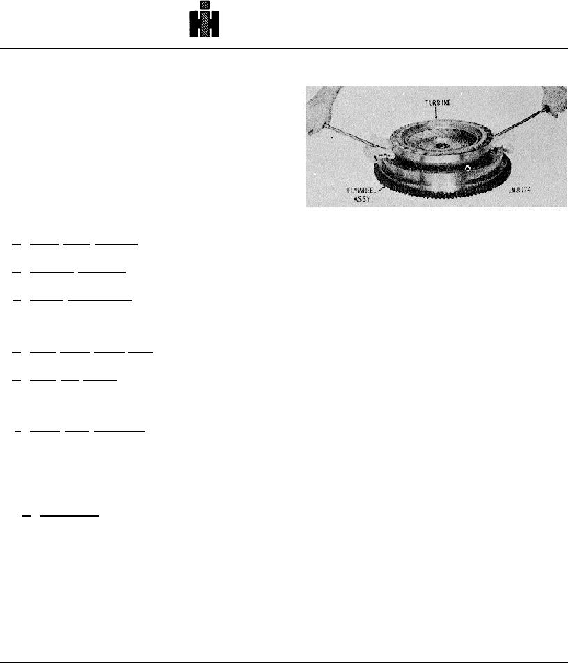
Fig. 6-1. Removing converter turbine 6 from flywheel.
a. Tools, Parts, Methods. Refer to paragraphs 4-2,
4-3 and 4-4.
(3) Remove ball bearing 6 (B, foldout 7) from
b. Cleaning, Inspection. Refer to paragraph 4-5 for
torque converter turbine 7, if parts replacement is
cleaning and inspection procedures.
necessary.
(4) Re move the lockup clutch back plate from the
c. Torque Specifications. The specific torque value
flywheel (fig. 6-2). Remove the key from the recess in
for each threaded fastener is stated at each assembly
the flywheel bore.
step. Torque values are also presented in paragraph 4-
9.
(5) Remove the lockup clutch plate (fig. 6-2).
d. Wear Limits, Spring Data. Refer to Section 8 for
(6) Remove the lockup clutch piston (fig. 6-3).
wear limits and spring data.
Remove the sealring from the piston outer groove.
e. Plugs and Fittings. Prior to installation, apply a
(7) Remove the sealring from the inner hub of the
small amount of nonhardening sealant (or Teflon tape)
flywheel (fig. 6-3).
into the threads of each plug. Tighten the plugs
(8) If replacement is necessary, remove the
sufficiently to prevent leakage.
starter ring gear from the flywheel after noting whether
the gear chamfers are toward the front or rear of the
f. Clutch Pack Procedure. Soak the friction-faced
flywheel.
clutch plates in transmission fluid for a minimum of 2
minutes prior to assembly.
(9) If the sealring surface of the flywheel bore is
worn beyond 1. 007 inches diameter, rework the bore
6-3. FLYWHEEL, LOCKUP CLUTCH, CONVERTER
and install a sleeve (P/N 6881519) as shown in figure 6-
TURBINE
4.
(10) Cool the sleeve in dry ice for at least thirty
a. Disassembly (foldout 7)
minutes before installing.
Proper alinement during
(1) Position the flywheel assembly, front
installation is necessary to prevent damaging the bore
downward, on the work table (fig. 6-1).
and sleeve.
(2) Using two large screwdrivers or (prybars)
(11) Press the sleeve flush with surface X (fig. 6-4).
cushioned to prevent scratching(components)pry the
Be sure the internal chamfer is toward the rear side of
torque converter turbine free of the flywheel and lockup
the flywheel.
clutch (fig. 6-1).
NOTE
Refer to paragraph 6-2, above.
736