
TRUCK SERVICE MANUAL
TRANSMISSION
Para 6-3
HT 700D SERIES TRANSMISSIONS
Fig. 6-5. Components of control valve assembly
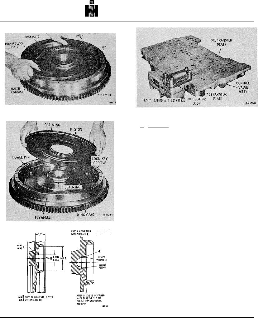
Fig. 6.2. Removing (or installing) lockup clutch back
plate .
b. Assembly
(1) If the starter ring gear was removed, install a
new gear, as follows.
(2) Install the starter ring gear after heating it
uniformly to 4000F (2040C) maximum temperature. Be
sure the chamfers of the teeth are facing the proper
direction for starter pinion engagement. The ring gear
must seat firmly against the shoulder on the flywheel.
(3) Lay the flywheel on the assembly table, with
the cavity side upward, and install the sealring onto the
hub (fig. 6-3).
(4) Install a sealring on the outside diameter of the
lockup clutch piston and lubricate both sealrings.
(5) Place a pencil mark on the edge of the lockup
clutch piston opposite a dowel pin hole. Also place a
pencil mark in the flywheel bore, opposite a dowel pin.
Fig. 6.3. Installing lockup clutch piston.
(6) Install the lockup clutch piston into the
flywheel, alining the pencil marks, to engage the
recesses in the piston with the dowel pins (fig. 6-3). Be
certain the dowel pins are engaged.
(7) Install the lock key in the lock key groove of
the flywheel (fig. 6-2). Use oil soluble grease to retain it.
(8) Install the lockup clutch plate (fig. 6-2)
(9) Install the lockup clutch back plate, flat side
first, engaging the notch in the plate with the key in the
flywheel (fig. 6-2).
Fig. 6-4. Rework of flywheel-cross section view.
737