
TRUCK SERVICE MANUAL
TRANSMISSION
INSPECTION AND REBUILD
Para 6-3/6-4
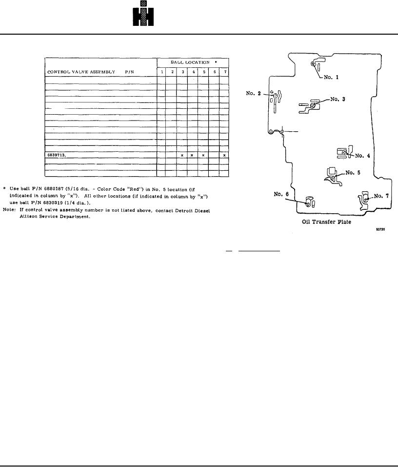
Fig. 6-6. Ball locations for control valve.
a. Disassembly (B, foldout 16)
(10) If ball bearing 6 (B, foldout 7) was removed,
press it onto the hub of turbine 7.
(1) If not removed previously, remove manual
(11) Carefully center the lockup clutch plate in the
selector valve 72. Stop bolt 62 must be removed before
flywheel. Install the torque converter turbine, engaging
valve 72 can be removed.
its hub splines with the internal splines of the lockup
(2) Position the valve assembly, modulator
clutch plate. Seat the ball bearing in its bore.
upward (fig. 6-5). Remove three bolts that retain the
modulator valve body, while holding the oil transfer plate
6-4. CONTROL VALVE BODY ASSEMBLY
and separator plate together.
CAUTION
(3) Lift off the modulator valve body and set it
aside, while retaining a grasp on the oil transfer and
The valve body assembly contains a number of
separator plates.
springs, some of which are similar and can be
(4) Invert the oil transfer and separator plates
mistakenly interchanged. Also, springs vary in
while holding them firmly together. Lay them on the work
valve bodies used on different models. If
table.
springs are not reinstalled in the same locations
(5) Lift the separator plate off the oil transfer plate.
from which removed, the calibration of valve
Compare check ball locations in the transfer plate to
body functions will be lost. For these reasons, it
those in the chart (shown in fig. 6-6), Make a sketch or
is recommended that each spring, at removal, be
list that will identify the ball sizes and locations (for
tagged with its item number in B, foldout 16.
reassembly). Remove the balls.
This will simplify correct reassembly of the valve
(6) Remove the lubrication pressure regulator
body components.
valve from the oil transfer plate as
738