
TRUCK SERVICE MANUAL
TRANSMISSION
Para 5-13
HT 700D SERIES TRANSMISSION
Fig. 5.44. Removing first clutch plates .
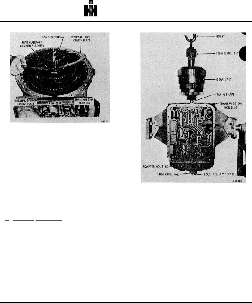
5-13. REMOVING CENTER SUPPORT, GEAR UNIT,
SECOND CLUTCH.
a. Supporting Gear Unit
(1) With the output end of the transmission
upward, install the adapter housing (less piston) and
gasket.
(2) Place center support compressor bar 8 (fig. 4-
2) across the rear of the adapter housing so that the
Fig. 5-45. Removing gear unit assembly
center hole in the bar will engage the mainshaft (fig. 5-
45).
(3) Install center support lifting bracket 5 (fig. 4-2)
(3) Install two bolts to retain the tool and the
into the recess between the step-joint sealrings on the
adapter housing to the transmission housing.
center support hub (fig. 5-35).
b. Removing Components
(1) Invert the transmission housing, converter end
(4) Lift carefully, straight upward, on the lifting
upward. Remove the center support anchor bolt and
bracket to remove the center support assembly.
washer (figure 5-33).
CAUTION
(2) Remove the snapring that retains the center
support assembly (fig. 5-34).
This is a selective
The center support is fitted to the transmission
thickness snapring.
case with very little clearance. It may bind in the
case if the case is cold. Heat the case slightly, if
necessary. Do not use a torch to heat the case.
A heat lamp, or a current of warm air, is
sufficient. If the support assembly starts upward
and then binds, tap it downward and lift again.
734