
TRUCK SERVICE MANUAL
TRANSMISSIONS
DISASSEMBLY
Para 5-6
(2) Carefully lift the stator assembly from the turbine
shaft. Refer to paragraph 6-8 for rebuild of the stator
assembly.
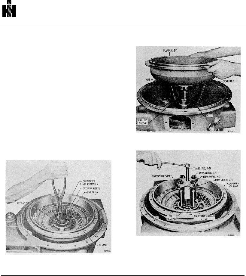
(3) Remove the snapring and splined spacer from
the converter ground sleeve (fig..5-18).
(4) Remove the converter pump from the converter
housing (fig. 5-19) After S/N 2082, remove the converter
pump (fig. 5-20), using tool J25007, as follows.
(5) Using figure 5-20 as a guide, place puller sleeve
51 (fig. 4-3) onto the converter ground sleeve.
(6) Insert the feet of leg and nut assemblies 49 (fig.
4-3) between the balls of the bearing assembly, spacing
them 90 apart
(7) Rotate the legs to make the feet bear against
both the inner and outer bearing race grooves. Install
puller head 50 onto the legs, tightening the nuts evenly.
(8) Install center screw 52 and tighten I it by hand
Fig. 5-19 Removing torque converter pump
until it is centered on sleeve 51. Hold the pump
assembly, and tighten the center screw until the pump
assembly will lift off the ground sleeve. Refer to
paragraph 6-9 for rebuild of the pump assembly
Fig. 5-20 Removing torque converter pump
using special tool
729