
TRUCK SERVICE MANUAL
TRANSMISSIONS
HT 700D SERIES TRANSMISSION
Para 5-5
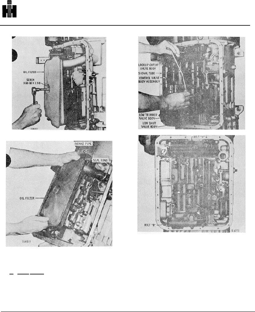
Fig. 5-12. Removing signal tube
Fig. 5-11. Removing oil filter
Fig. 5-13. Valve body assembly
(3) Remove the five bolts remaining in the low
trimmer valve body (fig. 5-14). Remove the low trimmer
Fig. 5-11. Removing oil filter
valve body.
move the oil filter (fig. 5-11), sealring, and the oil filter
(4) Remove the one remaining bolt iin the low shift
spacer.
valve body. Remove the low shift valve body.
b. Valve Bodies
(1) Remove the signal tube (fig. 5-12).
(5) Refer to paragraphs 6-5 and 6-6 for rebuild of the
low trimmer and shiftvalve bodies.
(2) Remove bolts A and B (fig. 5-13). Install two 1/4-
20 guide bolts 39 (fig. 4-3) into positions A and Bo
(6) Remove the seven remaining bolts that retain the
cover plate, Remove the cover plate.
727