
TRUCK SERVICE MANUAL
TRANSMISSION
HT 700D SERIES TRANSMISSIONS
Para 6-4/6-6
NOTE
Use extreme care that the separator plate and oil
transfer plate do not separate.
A slight
separation could dislocate the check valve balls
and cause malfunction of the transmission.
(26) Install the assembled modulator valve onto the
oil transfer plate as shown in figure 6-5. Install three 1/4-
20 x 2 1/2-inch bolts to retain the modulator body, oil
transfer plate, separator plate and control valve
assembly as a unit. Do not tighten the bolts at this time.
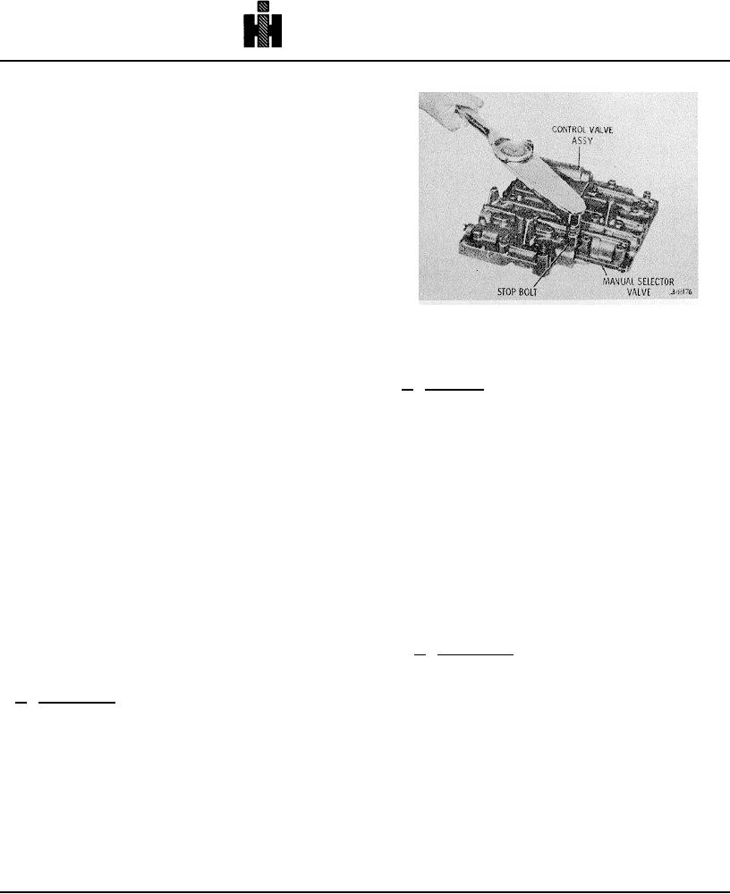
(27) Aline the bolt holes in the control valve
assembly with those in the separator plate and oil
Fig. 6-8 Tightening selector valve stop bolt .
transfer plate. When all bolt holes are alined, tighten the
NOTE
bolts installed in (26), above, to 9 to 11 pound feet (12 to
15 Nm) torque.
Refer to paragraph 6-2, above.
(28) Install manual selector valve 53 (fig. 6-7) into
b. Assembly (A, foldout 17)
bore O of the control valve body.
(1) Install low clutch trimmer valve 21, recessed
(29) Valve 53 must be positioned so that its flat
end first, into valve body 19.
side is upward (when assembly is positioned as in fig. 6-
NOTE
8).
Valves, when installed dry, should move by their
(30) Install stop bolt 64 (B, foldout
16) into
own weight.
control valve assembly. The flat end of the
bolt must
aline with the flat side of the selector valve
(fig. 6-8).
(2) Install trimmer plug 22.
Tighten the stop bolt to 36 to 43 pound feet
(49 to 58
(3) Install springs 23 and 24, valve stop 25, and
Nm) torque.
retainer plug 26.
NOTE
(4) Compress springs 23 and 24, and install
Refer to paragraph 3-11 for adjustment of shift
retainer pin 20 to secure plug 26.
speed points.
(31) To prevent dust or dirt from contaminating the
6-6. LOW SHIFT VALVE BODY ASSEMBLY
valve assembly, place it in a plastic bag until ready for
installation onto the transmission.
a. Disassembly (A, foldout 17)
(1) While holding inward against valve stop 9,
6-5. LOW TRIMMER VALVE BODY ASSEMBLY
remove retainer pin 5.
a. Disassembly (A, foldout 17)
NOTE
(1) Press inward on retainer plug 26, and remove
In earlier models, valve stop 9 consisted of two
retainer pin 20.
separate pieces.
(2) Release pressure, and remove plug 26,
springs 23and 24, valve stop 25, plug 22 and valve 21.
(2) Release spring pressure, and remove valve
stop 9, spring 8, and relay valve 7.
NOTE
Mark adjusting ring 15 and valve body 3 so that
ring 15 can be reinstalled at the same position as
before removal.
743