
TRUCK SERVICE MANUAL
TRANSMISSION
INSPECTION AND REBUILD
Para 6-24//6-25
the parts of the pinion group with the pinion pin holes in
the carrier.
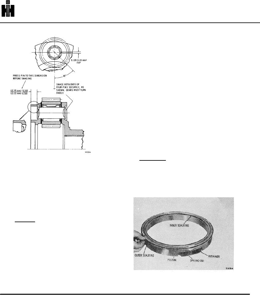
(3) Install pinion pin 20 and press it through the
carrier and pinion group to the dimension shown in figure
6-63.
NOTE
Pins must be a tight, to moderately tight, press
fit (when parts are at normal temperatures).
(4) Install the remaining pinion groups and pins in
the manner described above.
(5) Support each pinion pin on an 0. 812-inch (20.
62 mm) (approx) anvil. Using a suitable punch, swage
the pin firmly against the carrier to form the pattern
shown in figure 6-63. After swaging, each pinion must
rotate freely with 0. 008 to 0. 031 inch (0. 203 to 0. 787
mm) end play.
6-25. ADAPTER HOUSING ASSEMBLY
a. Disassembly (A, foldout 15)
Fig. 6-63. Components of low planetary carrier
assembly
(1) Position the assembly, piston assembly upward. Lift
out the piston assembly (includes items 3 through 8).
(3) Remove as a unit, each of the four pinion
groups consisting of pinions 23, thrust washers 21 and
(2) Remove the inner and outer sealrings from the piston
24, and needle roller bearings 22. Remove bearings
(Fig. 6-64).
from pinion bores.
NOTE
Refer to paragraph 6-2, above.
b. Assembly (A, foldout 15)
NOTE
To facilitate assembly, it is permissible to
freeze pinion pin 20 or heat carrier 19 before
pinion pin installation.
(1) Install bearings 22 into the bore of each pinion
23. Place a steel thrust washer 24 (first), and a bronze
washer 21 (last) onto each face of pinions 23.
Fig. 6-64. Removing (or installing) first clutch piston seal
(2) Position carrier 19 in a press, and place a pinion
ring
group (as assembled in (1), above) into the carrier. Aline
764