
TRUCK SERVICE MANUAL
TRANSMISSION
Para 6-22
HT 700D SERIES TRANSMISS IONS
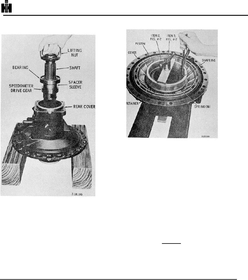
Fig.6-53. Removing (or iInstalling) snap ring that retains
piston in rear cover
(9) Remove the spring retainer and30 springs
(Fig. 6-53).
(10) Remove the clutch piston (fig 6-53).
Remove the inner and outer sealrings from the piston.
(11) If the speedometer driven gear bushing
requires replacement, remove it. Thread remover 22
(Fig. 4-2).into the bushing (Fig. 6-54). Attach slide
hammer 19 (fig.4-2) to remover 22 and remove the
bushing.
Fig. 6-52. Removing (or Installing) output shaft
(12) Remove any remaining parts (dowel pins,
snapring, governor support pin, plugs) that require
(6) Support the front of the speedometer drive
replacement, from the rear cover (Fig. 6-54).
gear, and press the output shaft from the gear, spacer
sleeve and bearing (Fig. 6-52).
NOTE
(7) If orifice plug 20 (A, foldout 16) or bushing 22
Refer to paragraph 6-2, above.
requires replacement remove either or both as required.
(8) Using compressor components 2 and 3 (Fig.
b. Assembly (A, foldout 16)
4-2), compress the spring retainer and springs (Fig. 6-
53). Remove the snapring, and remove the compressor.
(1) If removed, replace the dowelpins in the mounting
face of the rear cover (fig.6-55). The dowel pins project
0. 360 to 0.400 inch (9.15 to 10.16 mm) above the face
of the cover.
759