
TRUCK SERVICE MANUAL
TRANSMISSION
INSPECTION AND REBUILD
Para 6-22
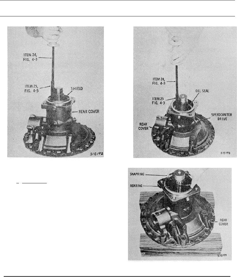
Fig. 6-50 Removing output shaft rear oil seal
Fig. 6-49 Removing dust shield from rear cover
6-22. REAR COVER ASSEMBLY
a. Disassembly (A, foldout 16)
(1) Using remover 24 (fig. 4-3), remove the dust shield
from the rear cover (fig. 6-49).
(2) Using remover 24 (fig. 4-3), remove the output shaft
oil seal from the rear cover (fig. 6-50).
(3) Re move the speedometer drive components from
the rear cover (fig. 6-50).
(4) Remove the snapring that retains the rear output
shaft bearing (fig. 6-51).
(5) Remove the rear output shaft, and its attached parts,
from the rear cover (fig. 6-52).
(6)
Fig. 6-51 Removing (or installing) output shaft bearing
snapring
758