TRUCK SERVICE MANUAL
TRANSMISSION
INSPECTION AND REBUILD
Para 6-2216-23
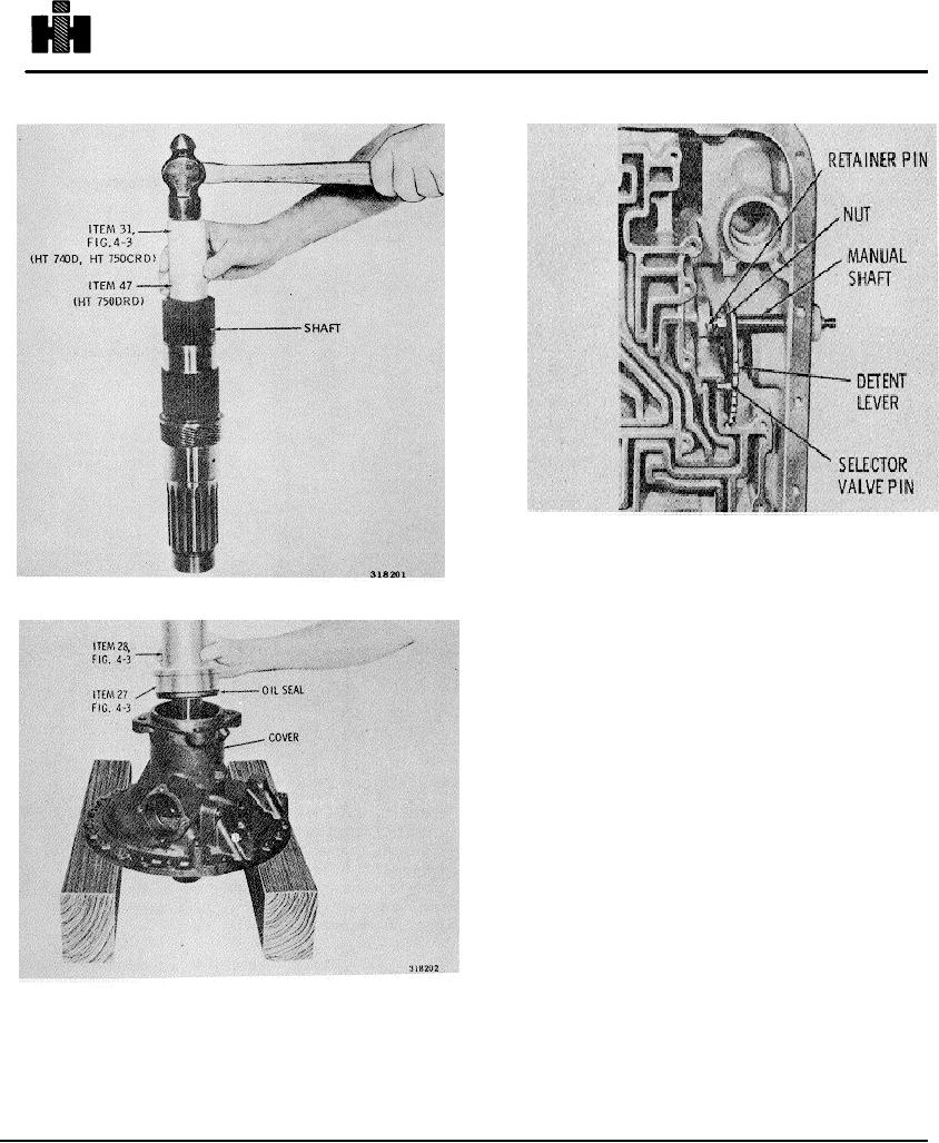
Fig. 6-61. Manual shaft components
Fig. 6-59. Installing output shaft bushing
(14) Coat the outer circumference of dust shield 32
(A, foldout 16) with nonhardening sealer. Install the
shield, flat side first, into the rear cover. The rear edge of
the shield must be flush with, to 0.040 inch (1. 01 mm)
below, the rear surface of the cover.
(15) If available, install the output flange after coating
the oil sealinner circumference with high-temperature
grease.
Tighten the flange retaining nut 31 (A, foldout 16)
to750 to 1000 pound feet (1017 to 1356 Nm) torque.
(16) Install the speedometer drive components (Fig.
6-50).
6-23. TRANSMISSION HOUSING
a. Disassembly (A, foldout 14)
(1) To remove the manual detent lever, use the
following procedure.
Remove the retainer pin and
locknut (Fig. 6-61).
(2) Hold the detent lever in one hand and remove the
manual shaft by carefully pulling the shaft through the oil
seal in the housing. Remove the detent lever.
CAUTION
If the shaft is burred or rough, smooth it with
crocus cloth or a honing stone, before
removal, to avoid scratching the housing bore.
762

