
TM 5-3805-264-13&P
0023
DISASSEMBLY - Continued
NOTE
Perform Steps 4 through 10 to disassemble control box.
4.
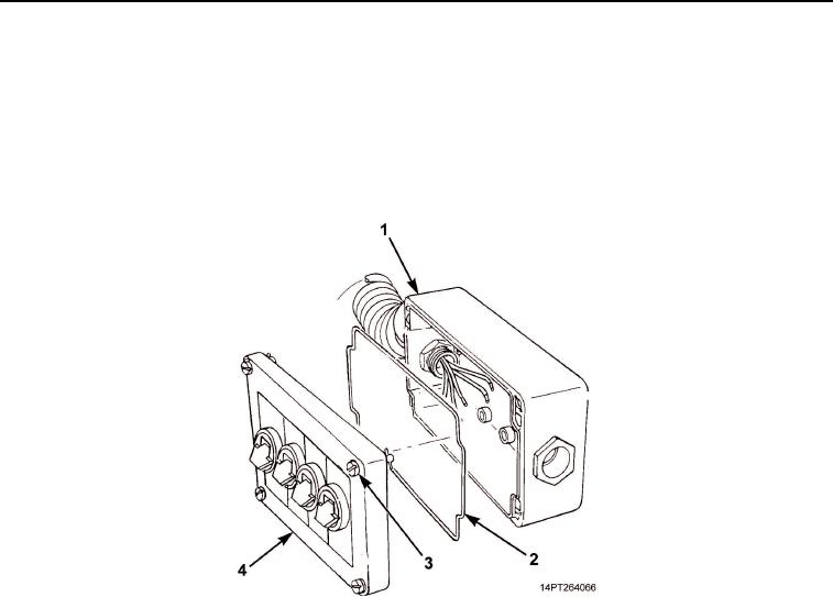
Loosen four twist-lock screws (Figure 2, Item 3) and remove cover (Figure 2, Item 4) from control box
(Figure 2, Item 1).
5.
Remove gasket (Figure 2, Item 2) from cover (Figure 2, Item 4).
Figure 2. MCS Control Box Cover Disassembly.
NOTE
Perform Steps 6 through 8 for each of four switches.
6.
Loosen two screws (Figure 3, Item 3) and disconnect two wires (Figure 3, Item 2) from switch
(Figure 3, Item 4).
NOTE
Note position of switch and retainer for assembly.
7.
Remove switch (Figure 3, Item 4) and retainer (Figure 3, Item 5) from switch housing (Figure 3, Item 8).
8.
Remove ring (Figure 3, Item 6), switch housing (Figure 3, Item 8), and data plate (Figure 3, Item 7) from
cover (Figure 3, Item 1).
03/15/2011Rel(1.10)root(maintwp)wpno(M1001026413)