
TM 5-3805-264-13&P
0023
ASSEMBLY
NOTE
Perform Steps 1 through 7 to assemble control box.
1.
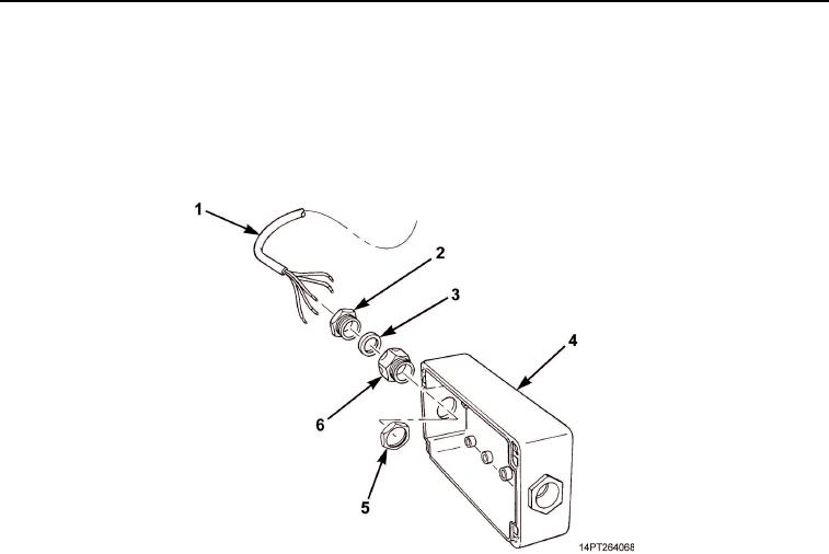
Install bushing (Figure 5, Item 6) and nut (Figure 5, Item 5) on control box (Figure 5, Item 4).
2.
Install end of cable (Figure 5, Item 1), grommet (Figure 5, Item 3), and locking plug (Figure 5, Item 2).
Figure 5. MCS Control Box Cable Assembly.
NOTE
Perform Steps 3 through 5 for each of four switches.
3.
Install data plate (Figure 6, Item 7), switch housing (Figure 6, Item 8), and ring (Figure 6, Item 6) on cover
(Figure 6, Item 1).
4.
Install retainer (Figure 6, Item 5) and switch (Figure 6, Item 4) on switch housing (Figure 6, Item 8).
5.
Connect two wires (Figure 6, Item 2) to switch (Figure 6, Item 4) and tighten two screws (Figure 6, Item 3).
03/15/2011Rel(1.10)root(maintwp)wpno(M1001026413)