
TM 5-3805-264-13&P
0023
DISASSEMBLY - Continued
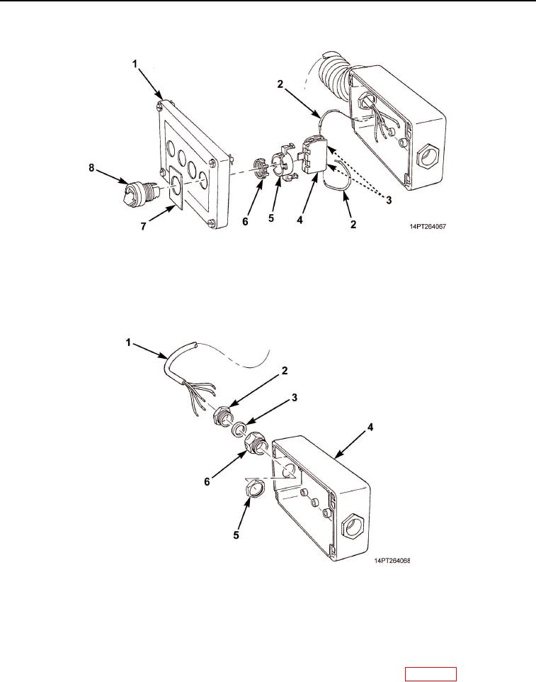
Figure 3. MCS Control Box Components Disassembly.
9.
Remove locking plug (Figure 4, Item 2), grommet (Figure 4, Item 3), and cable (Figure 4, Item 1) from
control box (Figure 4, Item 4).
10.
Remove nut (Figure 4, Item 5) and bushing (Figure 4, Item 6).
Figure 4. MCS Control Box Cable Disassembly.
END OF TASK
CLEANING AND INSPECTION
Clean and inspect components in accordance with General Maintenance Instructions (WP 0072).
END OF TASK
03/15/2011Rel(1.10)root(maintwp)wpno(M1001026413)