
TM 5-3805-264-13&P
0037
INSTALLATION - Continued
NOTE
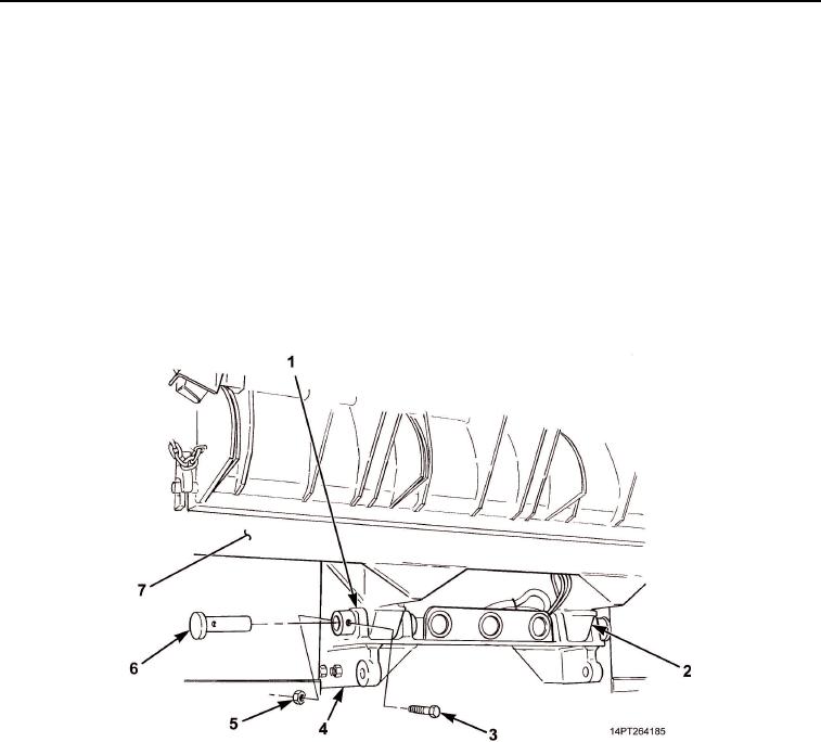
When positioning dump body on vehicle chassis, pay close attention to hydraulic cylinder
positioning and rear hinge assembly alignment.
4.
Lift dump body (Figure 6, Item 7) and position over vehicle chassis (Figure 6, Item 4). Lower body until rear
hinge (Figure 6, Item 1) and hinge pads (Figure 6, Item 2) are aligned and hydraulic cylinder is properly
positioned in recess at front of dump body.
5.
Install driver's side and passenger's side hinge pins (Figure 6, Item 6) in rear hinge (Figure 6, Item 1).
6.
Install two screws (Figure 6, Item 3) and new locknuts (Figure 6, Item 5) in rear hinge (Figure 6, Item 1) and
hinge pins (Figure 6, Item 6).
7.
Lower dump body (Figure 6, Item 7) onto vehicle chassis (Figure 6, Item 4). Remove lifting chains from rear
of dump body.
Figure 6. Hinge Pin Installation.
03/15/2011Rel(1.10)root(maintwp)wpno(M1004526413)