
TM 5-3805-264-13&P
0037
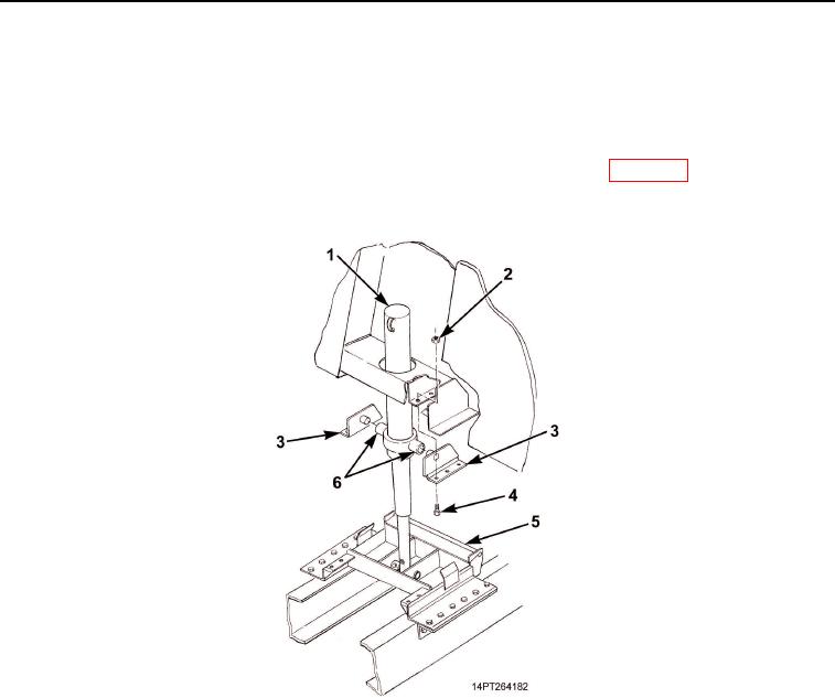
REMOVAL - Continued
4.
Remove six locknuts (Figure 3, Item 2) and screws (Figure 3, Item 4) from driver's side and passenger's
side mounting brackets (Figure 3, Item 3). Remove brackets from hydraulic cylinder pivots
(Figure 3, Item 6). Discard locknuts.
5.
Disengage Power Take Off (PTO) (TM 9-2320-363-10 or TM 9-2320-302-10). Lower hydraulic cylinder
(Figure 3, Item 1) by placing hydraulic control lever in cab in DOWN position (WP 0005). With hydraulic
cylinder lowered, place wooden blocks between base of cylinder and cylinder support frame
(Figure 3, Item 5) to provide support.
Figure 3. Mounting Bracket Removal.
03/15/2011Rel(1.10)root(maintwp)wpno(M1004526413)