
TM 5-3805-264-13&P
0066
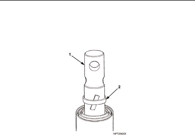
DISASSEMBLY - Continued
5.
Using overhead lifting device with nylon sling, raise plunger (Figure 4, Item 1) a few inches and apply tape
to a cleaned section of plunger.
6.
Lower and lift plunger (Figure 4, Item 1) to expose bottom guide ring (Figure 4, Item 2). Remove tape.
7.
Lower plunger (Figure 4, Item 1) and remove nylon sling. Remove bottom guide ring (Figure 4, Item 2) from
plunger. Discard bottom guide ring.
Figure 4. Guide Ring Removal.
8.
Using two small screwdrivers, remove bottom retaining ring (Figure 5, Item 3) from groove of sleeve
(Figure 5, Item 2). Position four hydraulic cylinder disassembly tools, equally spaced, between bottom
retaining ring and sleeve.
NOTE
Hydraulic cylinder disassembly tools will fall free as plunger, with bottom retaining ring, is
removed from sleeve.
9.
Remove plunger (Figure 5, Item 1) from sleeve (Figure 5, Item 3). Remove nylon sling and bottom retaining
ring (Figure 5, Item 2) from plunger.
03/15/2011Rel(1.10)root(maintwp)wpno(M1005126413)