
TM 5-3805-274-13&P
0022
REMOVAL
NOTE
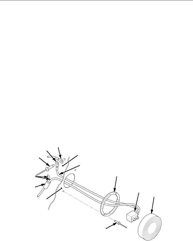
Right and left upper rear marker lamps are removed and installed
the same way. Only one upper rear marker lamp is shown.
1.
Turn lens/lamp (Figure 1, Item 8) one-quarter turn to left and remove lens/lamp (Figure 1, Item 8) from
mount plate (Figure 1, Item 6).
2.
Disconnect lamp plug (Figure 1, Item 7) from lens/lamp (Figure 1, Item 8).
3.
Cut splice conductor (Figure 1 Item 11) from black positive (+) wires (Figure 1, Item 12). Discard splice
conductor (Figure 1 Item 11).
4.
Remove blind rivet (Figure 1, Item 1) and two collars (Figure 1, Items 2 and 3) from frame
(Figure 1, Item 4). Side white ground (-) wire (Figure 1, Item 5) stays in frame (Figure 1, Item 4).
Discard blind rivet (Figure 1, Item 1).
5.
Remove two blind rivets (Figure 1, Item 9) and mount plate (Figure 1, Item 6) from mounting surface
(Figure 1, Item 10). Discard blind rivets (Figure 1, Item 9).
END OF TASK
INSTALLATION
1. Install mount plate (Figure 1, Item 6) on mounting surface (Figure 1, Item 10) with two new blind rivets
(Figure 1, Item 9).
2. Route white ground (-) wire (Figure 1, Item 5) through hole in mounting surface (Figure 1, Item 10) and
connect collars (Figure 1, Items 2 and 3) to frame (Figure 1, Item 4) with new blind rivet
(Figure 1, Item 1).
3. Connect black positive (+) wires (Figure 1, Item 12) with new splice conductor (Figure 1 Item 11).
4. Connect lamp plug (Figure 1, Item 7) into back of lens/lamp (Figure 1, Item 8).
5. Install lens/lamp (Figure 1, Item 8) over mount plate (Figure 1, Item 6) and turn lens/lamp
(Figure 1, Item 8) one-quarter turn to right.
3
2
4
1
5
6
12
11
7
8
10
9
Figure 1. Upper Rear Marker Lamp Assembly Removal and Installation.
END OF TASK
END OF WORK PACKAGE