
TM 5-3805-274-13&P
0023
NOTE
Right and left side marker lamps are removed and installed the same
way, only one side marker lamp is shown.
REMOVAL
1.
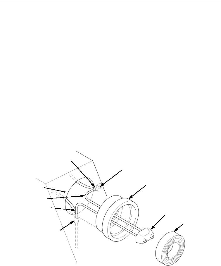
Using small screwdriver, pry lens/lamp (Figure 1, Item 5) from grommet (Figure 1, Item 3).
2.
Remove grommet (Figure 1, Item 3) from mounting surface (Figure 1, Item 9).
3.
Disconnect lamp plug (Figure 1, Item 4) from lens/lamp (Figure 1, Item 5).
4.
Cut splice conductor (Figure 1 Item 6) from black positive (+) wire (Figure 1, Item 7). Discard splice
conductor (Figure 1 Item 6).
5. Remove white ground (-) wire (Figure 1, Item 8) from blind rivet (Figure 1, Item 2) and collar
(Figure 1, Item 1), discard collar (Figure 1, Item 1), and pull white ground (-) wire (Figure 1, Item 8)
through hole in mounting surface (Figure 1, Item 9). Side marker ground (-) wire will stay in frame.
Discard blind rivet (Figure 1, Item 2).
END OF TASK
INSTALLATION
1. Route white ground (-) wire (Figure 1, Item 8) through hole in mounting surface (Figure 1 Item 9) and
connect both white ground (-) wires (Figure 1, Item 8) to mounting surface (Figure 1 Item 9) with collar
(Figure 1, Item 1) and new blind rivet (Figure 1, Item 2).
2. Connect black positive (+) wires (Figure 1, Item 7) with new splice conductor (Figure 1 Item 6).
3. Install grommet (Figure 1, Item 3) on mounting surface (Figure 1 Item 9).
4. Connect lamp plug (Figure 1, Item 4) into back of lens/lamp (Figure 1, Item 5).
5. Install lens/lamp (Figure 1, Item 5) in grommet (Figure 1, Item 3).
1
2
3
9
8
7
4
5
6
Figure 1. Side Marker Lamp Assembly Removal and Installation.
END OF TASK
END OF WORK PACKAGE