
TM 5-3805-274-13&P
0024
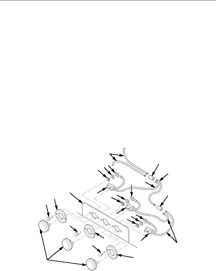
REMOVAL
1. Turn three lens/lamps (Figure 1, Item 10) one-quarter turn to left and remove three lens/lamps
(Figure 1, Item 10) from three mounts (Figure 1, Item 8).
2. Disconnect three lamp plugs (Figure 1, Item 7) from three lens/lamps (Figure 1, Item 10).
3. Cut black positive (+) wires (Figure 1, Item 4) from splice conductors (Figure 1, Items 5 and 6) near
lamp plugs (Figure 1, Item 7). Discard splice conductors (Figure 1, Items 5 and 6).
4. Remove three blind rivets (Figure 1, Item 9), white ground (-) wires (Figure 1, Item 3), washers
(Figure 1, Item 2), and lockwashers (Figure 1, Item 1). Discard lockwashers (Figure 1, Item 1) and blind
rivets (Figure 1, Item 9).
5. Remove three blind rivets (Figure 1, Item 9), mounts (Figure 1, Item 8), and lamp plugs
(Figure 1, Item 7) from mounting surface (Figure 1, Item 11). Discard blind rivets (Figure 1, Item 9).
END OF TASK
INSTALLATION
1. Install three mounts (Figure 1, Item 8) and lamp plugs (Figure 1, Item 7) on mounting surface
(Figure 1, Item 11) with three new blind rivets (Figure 1, Item 9).
2. Install three new blind rivets (Figure 1, Item 9) and three white ground (-) wires (Figure 1, Item 3) on
mounting surface (Figure 1, Item 11) with three new lockwashers (Figure 1, Item 1) and washers
(Figure 1, Item 2).
3. Install black positive (+) wires (Figure 1, Item 4) from three lamp plugs (Figure 1, Item 7) on black
positive (+) wire (Figure 1, Item 4) with new splice conductors (Figure 1, Items 5 and 6).
4. Connect three lamp plugs (Figure 1, Item 7) to three lens/lamps (Figure 1, Item 10).
5. Install three lens/lamps (Figure 1, Item 10) on three mounts (Figure 1, Item 8) and turn lens/lamps
(Figure 1, Item 10) one-quarter turn to right.
4
5
23
1
4
4
3
11
2
6
7
1
8
9
2 3
7
1
9
8
7
9
4
8
10
Figure 1. Lower Rear Marker Lamp Assembly Removal and Installation.
END OF TASK
END OF WORK PACKAGE